Boundary acoustic wave device

A technology of acoustic wave devices and boundaries, applied in the direction of electrical components, impedance networks, etc., can solve problems that are difficult to meet the boundary acoustic wave performance and characteristics

Active Publication Date: 2010-01-27
MURATA MFG CO LTD
View PDF10 Cites 0 Cited by
  • Summary
  • Abstract
  • Description
  • Claims
  • Application Information

AI Technical Summary

Problems solved by technology

[0015] However, due to the limitation of materials that can satisfy the above conditions, it is difficult to satisfy the above-mentioned various performances and characteristics required for boundary acoustic waves

Method used


Image

  • Boundary acoustic wave device
  • Boundary acoustic wave device
  • Boundary acoustic wave device

Examples


example 1

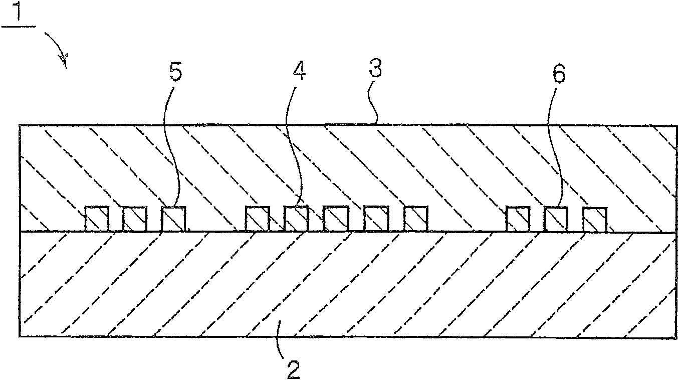
[0157] As piezoelectric material 2, LiNbO with Euler angles (0°, 90°, 0°) was prepared 3 substrate, i.e., the Y-directed plated X-propagated LiNbO 3 substrate. By utilizing LiNbO 3 substrate, which can obtain excellent piezoelectric properties. In addition, as a material for forming the dielectric substance 3, SiO 2 . SiO can be easily formed by 2 thin film formation, due to the LiNbO having shifted 3 Positive temperature coefficient of frequency TCF of negative TCF, SiO 2 The temperature characteristics can be improved.

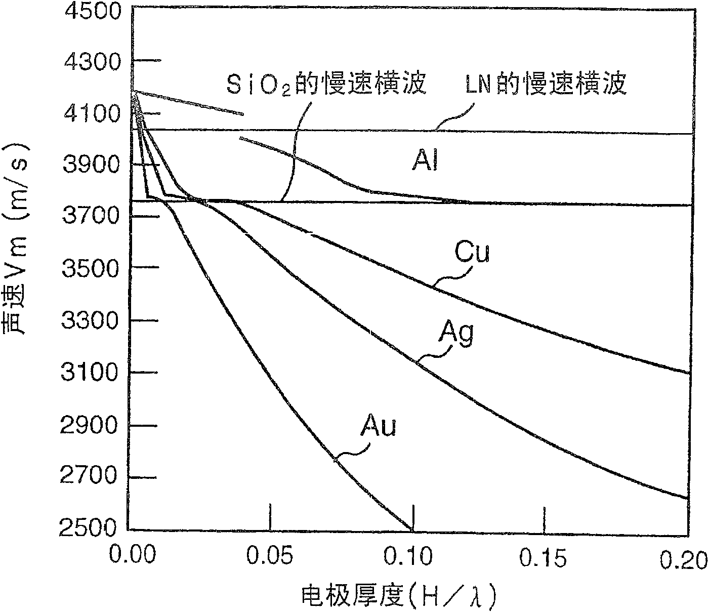
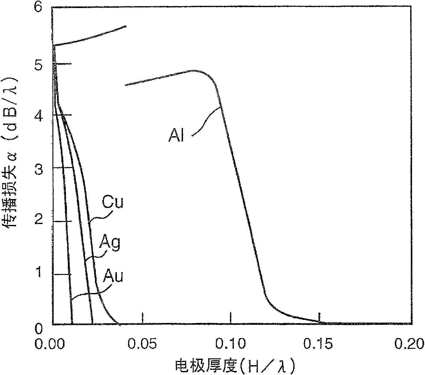
[0158] By using various electrode materials with different densities, an electrode was formed between the piezoelectric substance 2 and the dielectric substance 3, and the relationship between the electrode thickness and the sound velocity V, the electromechanical coefficient k 2 , the relationship between propagation loss α, frequency temperature coefficient TCF and power flow angle PFA. Figures 2 to 6 Results are shown.

[0159] By based on "A m...

example 2

[0182] Based on the results obtained in Example 1 above, experimentally formed figure 1 Boundary acoustic wave resonators shown and having the structures shown in Table 3 below. Figure 9 The frequency characteristics of the boundary acoustic wave resonator thus formed are shown in .

[0183] table 3

[0184] project

detail

structure

SiO 2 / Au / LiNbO 3

SiO 2 thickness

7.5λ

Au thickness

0.035λ

IDT, reflector period λ

3.2μm

IDT configuration

Ordinary single strap, 50 pieces, open

Length 25λ

reflector configuration

Ordinary single strap, 40 pieces, open

Length 25λ

[0185] In the above boundary acoustic resonator, the impedance ratio, that is, the ratio of the impedance at the antiresonance point to the impedance at the resonance point is 45.6dB, and the difference between the resonance frequency and the antiresonance frequency is 8.1%; therefore, it is preferred the ...

example 3

[0189] As in the case of the SH-type boundary acoustic wave, the above-mentioned spurious signal response generated around the antiresonant frequency in Example 2 is limited to the SiO 2 and LiNbO 3 The Stoneley wave response around the electrode at the boundary between them. Since the sound velocity of the Stoneley wave is lower than that of the SH-type boundary acoustic wave in many cases, even when the thickness of the electrode is small compared with the case of the SH-type boundary acoustic wave, the Stoneley wave is expressed as a boundary acoustic wave.

[0190] For example, when cutting X propagation in Y direction (represented by Euler angles (0°, 90°, 0°)) LiNbO 3 SiO with a sufficiently large thickness is formed on the substrate 2 film so as not to excite surface acoustic waves such as Rayleigh waves or first leaky waves, and the Au electrodes are placed on the LiNbO 3 Substrate and SiO 2 Between films, the SH-type boundary acoustic wave has a large attenuation ...


PUM


Abstract

An elastic boundary wave device employing an SH type elastic boundary wave having a large electromechanical coupling coefficient, a low propagation loss, a small power flow angle, a temperature coefficient of frequency TCF in an appropriate range, and a simple structure which can be produced through a simple process. A dielectric is deposited on one side of a piezoelectric and an IDT and a reflector are arranged as electrodes on the boundary of the piezoelectric and the dielectric, wherein the thickness of the electrodes is set such that the sound velocity of the SH type elastic boundary wave becomes lower than the sound velocity of a slow transverse wave propagating through the dielectric and the sound velocity of a slow transverse wave propagating through the piezoelectric.

Description

technical field [0001] The present invention relates to a boundary acoustic wave device utilizing SH-type boundary acoustic waves, and more particularly, to a boundary acoustic wave device having a structure in which electrodes are provided at the boundary between a piezoelectric substance and a dielectric substrate. Background technique [0002] So far, various surface acoustic wave devices have been used for RF and IF filters in mobile phones, resonators in VCOs, and VIT filters in TVs. Surface acoustic wave devices use Rayleigh waves or first leaky waves propagating along the surface of a medium. [0003] Since it propagates along the surface of the medium, surface acoustic waves are sensitive to the surface conditions of the medium. Therefore, in order to protect the surface of the medium along which the surface acoustic wave propagates, the surface acoustic wave element has been sealed in a housing having a cavity portion in which the above-explained surface is placed....

Claims


Application Information

Patent Timeline
Patent Type & Authority Patents(China)
IPC IPC(8): H03H9/25H03H9/145
Inventor 神藤始
Owner MURATA MFG CO LTD
Why Eureka
Try Eureka