Elastic wave device including a high acoustic velocity film and a low acoustic velocity film

a technology of acoustic wave and a thin film, applied in the direction of piezoelectric/electrostrictive devices, piezoelectric/electrostrictive/magnetostrictive devices, electrical devices, etc., can solve the problem of large propagation loss, surface acoustic wave energy leaked to the dielectric substrate, and the device cannot effectively confine the surface acoustic wave within the piezoelectric thin film, etc. problem, to achieve the effect o

Active Publication Date: 2017-04-11
MURATA MFG CO LTD
View PDF23 Cites 2 Cited by
  • Summary
  • Abstract
  • Description
  • Claims
  • Application Information

AI Technical Summary

Benefits of technology

[0007]Preferred embodiments of the present invention provide elastic wave devices with favorable characteristics.
[0042]In an elastic wave device according to another specific aspect of various preferred embodiments of the present invention, the acoustic velocity of the bulk wave propagating in the support substrate is lower than the acoustic velocity of the bulk wave propagating in the high acoustic velocity film. In this case, because the acoustic velocity in the substrate is lower, the high order mode is more surely leaked toward the substrate side. This makes it possible to more effectively reduce or prevent an influence of the high order mode.
[0043]An elastic wave device according to still another specific aspect of various preferred embodiments of the present invention further includes a second low acoustic velocity film. The second low acoustic velocity film is laminated between the support substrate and the high acoustic velocity film. Furthermore included is the second low acoustic velocity film in which a bulk wave propagates at a lower acoustic velocity than the bulk wave that propagates in the piezoelectric film. In this case, the high order mode is likely to be leaked to the second low acoustic velocity film. Accordingly, the high order mode is leaked more by the second low acoustic velocity film. As such, the degree of freedom in selecting a material for the support substrate is increased.
[0045]In elastic wave devices according to various preferred embodiments of the present invention, a high acoustic velocity film and a low acoustic velocity film are disposed between a support substrate and a piezoelectric film. Further, because energy concentration ratios of the main mode and the high order mode are respectively within the above-specified ranges in an upper structure section including the high acoustic velocity film, energy of the elastic wave in use is effectively confined in a portion where the piezoelectric film and the low acoustic velocity film are laminated. In addition, the high order mode which is spurious can be leaked toward the support substrate side of the high acoustic velocity film, thus making it possible to suppress the high order mode spuriousness. As such, favorable resonance characteristics, filter characteristics, and so on are obtained by the elastic wave in use. Moreover, it is possible to significantly reduce or prevent an undesirable response by the high order mode.

Problems solved by technology

However, a considerably large propagation loss occurs, and the surface acoustic wave cannot be effectively confined within a piezoelectric thin film.
As such, energy of the surface acoustic wave device is leaked to the dielectric substrate.
This causes a problem such that characteristics of an elastic wave device are degraded.

Method used


Image

  • Elastic wave device including a high acoustic velocity film and a low acoustic velocity film
  • Elastic wave device including a high acoustic velocity film and a low acoustic velocity film
  • Elastic wave device including a high acoustic velocity film and a low acoustic velocity film

Examples


first structure example

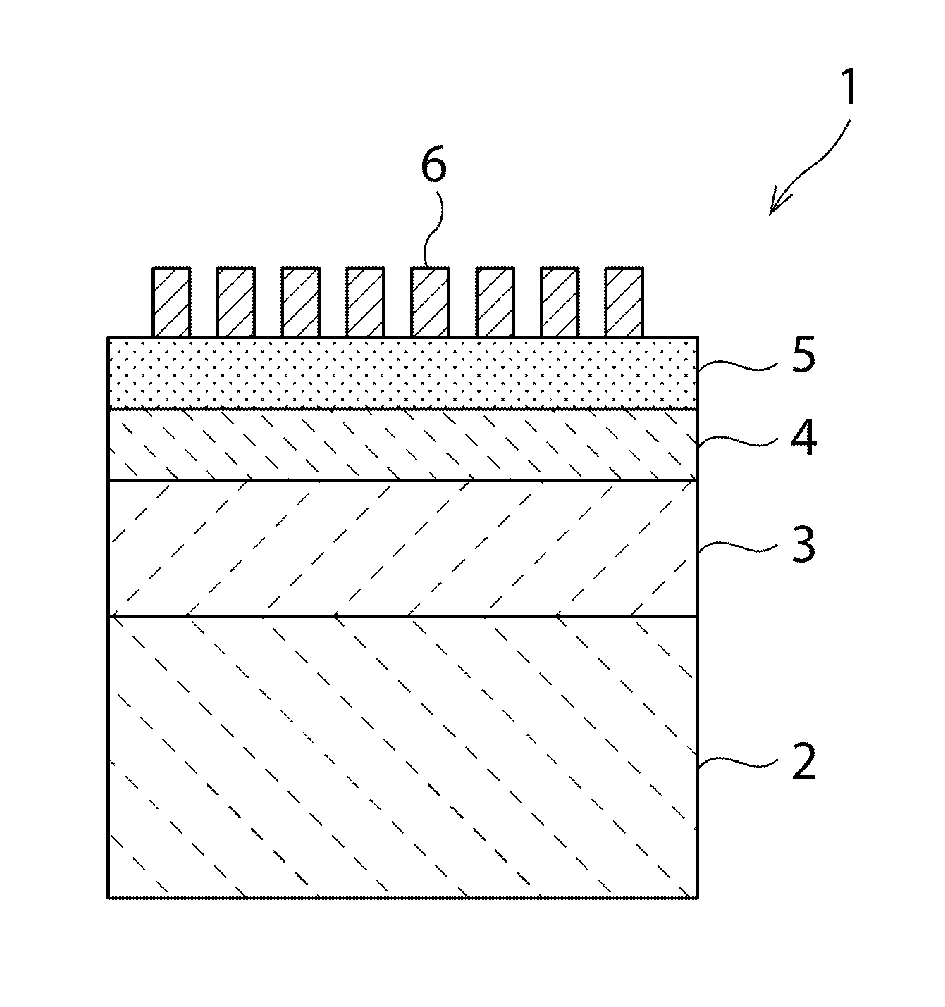
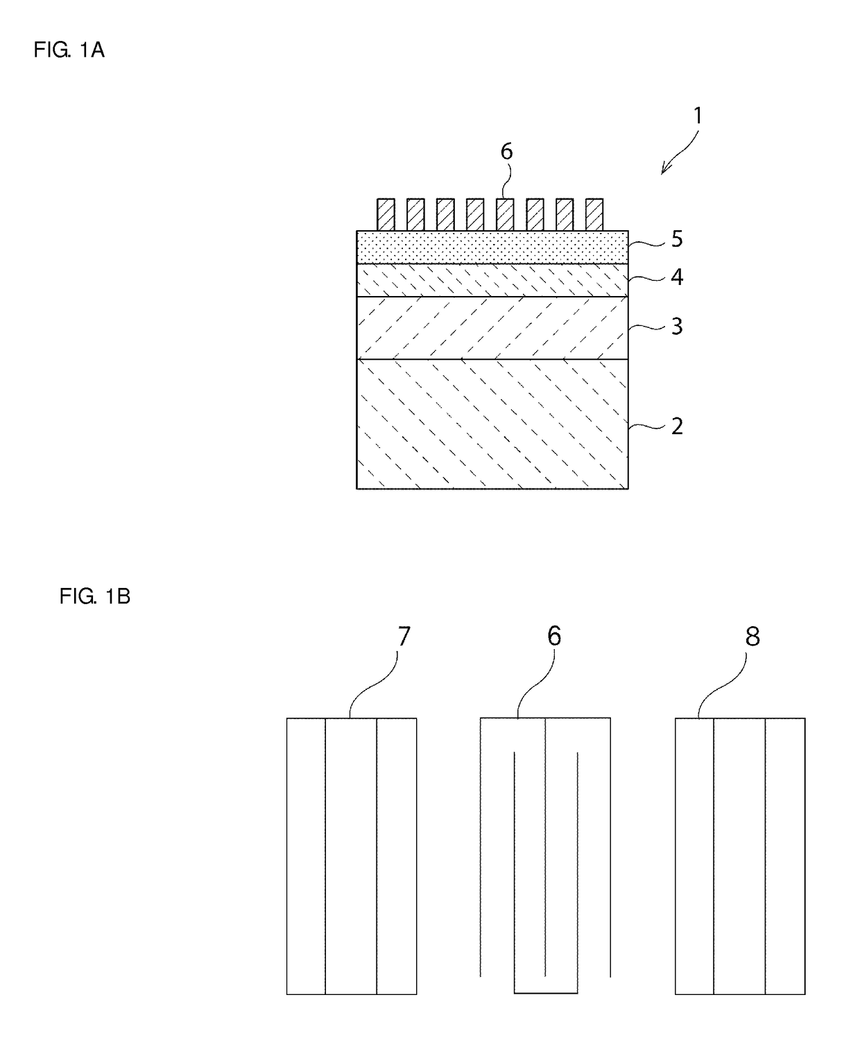
[0118]In a first structure example, as described in order from top to bottom the structure includes: the IDT electrode 6: Al film, thickness about 0.08λ / the piezoelectric film 5: Y-cut LiTaO3 single crystal, thickness about 0.25λ / the low acoustic velocity film 4: SiO2, thickness about 0.35λ / the high acoustic velocity film 3: aluminum nitride film, acoustic velocity about 5800 m / s.

[0119]FIG. 11 is a diagram illustrating a relationship between a film thickness of a high acoustic velocity film and acoustic velocity of a main mode in the case in which acoustic velocity in the high acoustic velocity film is about 5800 m / s. A curved line in FIG. 11 indicates acoustic velocity at a time when the main mode begins to leak in a case in which the acoustic velocity in the high acoustic velocity film is about 5800 m / s. In a region above the curved line, the main mode leaks so that favorable elastic wave characteristics cannot be obtained. Meanwhile, in a case in which the acoustic velocity of th...

second structure example

[0123]In a second structure example, as described in order from top to bottom the structure includes: the IDT electrode 6: Al film, film thickness having been varied / the piezoelectric film 5: Y-cut LiTaO3 single crystal, film thickness about 0.01λ to about 0.50λ / the low acoustic velocity film 4: silicon oxide, film thickness about 0.05λ to about 2.00λ / the high acoustic velocity film 3: various types of high acoustic velocity films for acoustic velocity about 4200 m / s to about 6000 m / s, film thickness not more than about 1.6λ / the support substrate 2: glass substrate.

[0124]In the same manner as in the case in which the diagram in FIG. 10 was derived, a relationship between the high acoustic velocity film thickness and the high order mode acoustic velocity was plotted in a case in which the energy concentration ratio of the high order mode is about 99.5%. The result thereof is shown in FIG. 20. Using the result shown in FIG. 20, the relationship was preferably set so that the energy co...


PUM


Abstract

An elastic wave device includes a high acoustic velocity film configured such that a bulk wave propagates at a higher acoustic velocity than an elastic wave that propagates in a piezoelectric film, a low acoustic velocity film configured such that a bulk wave propagates at a lower acoustic velocity than a bulk wave that propagates in the piezoelectric film is laminated on the high acoustic velocity film, the piezoelectric film is laminated on the low acoustic velocity film, and an IDT electrode is laminated on one surface of the piezoelectric film. In an upper structure section, an energy concentration ratio of a main mode which is an elastic wave is not less than about 99.9% and an energy concentration ratio of a high order mode which is spurious is not more than about 99.5%.

Description

BACKGROUND OF THE INVENTION[0001]1. Field of the Invention[0002]The present invention relates to elastic wave devices preferably for use in resonators, band-pass filters, and so on, more specifically, elastic wave devices having a structure in which another material is laminated between a support substrate and a piezoelectric layer.[0003]2. Description of the Related Art[0004]Elastic wave devices have been used as resonators, band-pass filters, and the like for years, and recently, they are being requested to operate at higher frequencies than before. Japanese Unexamined Patent Application Publication No. 2004-282232 discloses a surface acoustic wave device in which, on a dielectric substrate, a hard dielectric layer, a piezoelectric film, and an IDT (interdigital transducer) electrode are laminated in that order. In the disclosed surface acoustic wave device, the hard dielectric layer is disposed between the dielectric substrate and the piezoelectric film so as to raise acoustic ve...

Claims


Application Information

Patent Timeline
Patent Type & Authority Patents(United States)
IPC IPC(8): H03H9/25H03H9/205H03H9/17H01L41/047H01L41/08H03H9/02
CPCH03H9/25H01L41/047H01L41/0805H03H9/0222H03H9/02574H03H9/171H03H9/205H10N30/87H10N30/1051
Inventor IWAMOTO, HIDEKIKIDO, SYUNSUKE
Owner MURATA MFG CO LTD
Why Eureka
Try Eureka