

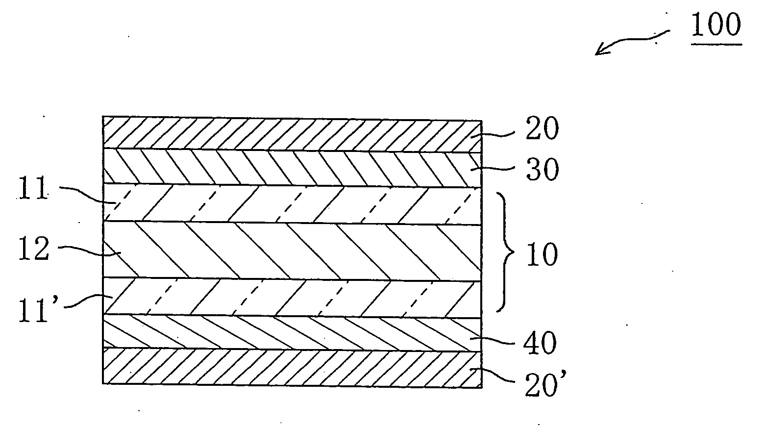
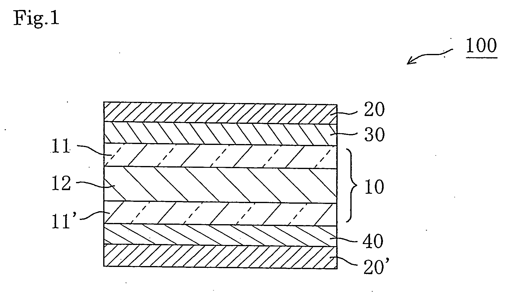
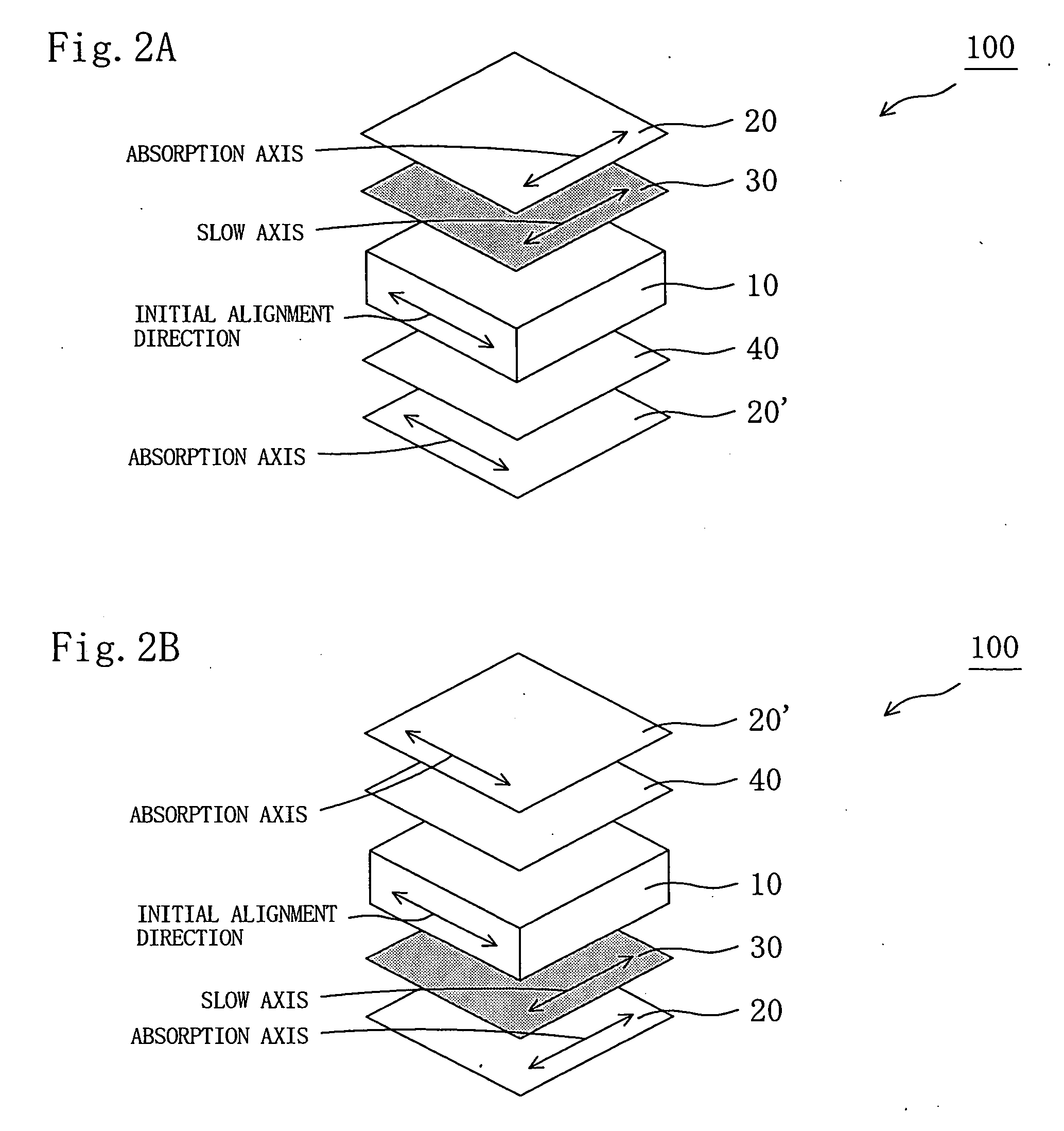
Liquid crystal panel and liquid crystal display apparatus
a liquid crystal display and liquid crystal technology, applied in the field of liquid crystal panels, can solve the problems of color shift, insufficient improvement of contrast ratio in an oblique direction, and deformation of the absorption axis of the polarizer, and achieve good display evenness and improved contrast ratio
- Summary
- Abstract
- Description
- Claims
- Application Information
AI Technical Summary
Benefits of technology
Problems solved by technology
Method used
Image

Examples
preparation example 1
[0176] A polycarbonate-based resin having a weight average molecular weight (Mw) of 60,000 and containing repeating units represented by the following formulae (5) and (6) (number average molecular weight (Mn) of 33,000, Mw / Mn of 1.78, weight ratio (A): (B) of 4:6) was obtained through a conventional method by using phosgene as a carbonate precursor, and (A) 2,2-bis(4-hydroxyphenyl)propane and (B) 1,1-bis(4-hydroxyphenyl)-3,3,5-trimethylcyclohexane as aromatic dihydric phenol components. 70 parts by weight of the polycarbonate-based resin and 30 parts by weight of a styrene-based resin (HIMER SB75, available from Sanyo Chemical Industries, Ltd.) having a weight average molecular weight (Mw) of 1,300 (number average molecular weight (Mn) of 716, Mw / Mn of 1.78) were added into 300 parts by weight of dichloromethane. The whole was mixed under stirring at room temperature for 4 hours, to thereby prepare a clear solution. The solution was cast on a glass plate and left standing at room t...
preparation example 2
[0182] A retardation film B was produced in the same manner as in Preparation Example 1 except that the stretch ratio was changed from 1.27 times to 1.30 times. Table 2 shows the stretching conditions and the properties of the obtained retardation film B.
preparation example 3
[0183] A retardation film C was produced in the same manner as in Preparation Example 1 except that the stretching temperature was changed from 147° C. to 146° C. and the stretch ratio was changed from 1.27 times to 1.25 times. Table 2 shows the stretching conditions and the properties of the obtained retardation film C.
PUM
| Property | Measurement | Unit |
|---|---|---|
| Temperature | aaaaa | aaaaa |
| Percent by mass | aaaaa | aaaaa |
| Percent by mass | aaaaa | aaaaa |
Abstract
Description
Claims
Application Information