Soldering apparatus

Inactive Publication Date: 2007-03-29
NIHON DEN NETSU KEIKI CO LTD
View PDF4 Cites 4 Cited by
  • Summary
  • Abstract
  • Description
  • Claims
  • Application Information

AI Technical Summary

Benefits of technology

[0015] The present invention has been made to overcome the above problems and it is, therefore, an object of the present invention to provide a system in which soldering of electronic parts can be carried out with high reliability by realizing a soldering apparatus which has improved maintainability and in which a leakage magnetic field and a stray current are reduced.

Problems solved by technology

In the soldering apparatus disclosed in U.S. Pat. No. 6,726,082, however, since the molten solder is used to attenuate a leakage magnetic field, in other words, the molten solder serves as a short ring (short band), a current may leak into the molten solder.

Method used


Image

  • Soldering apparatus
  • Soldering apparatus
  • Soldering apparatus

Examples


first embodiment

[0063] Description will be hereinafter made of a soldering apparatus according to a first embodiment of the present invention with reference to FIGS. 1 to 3.

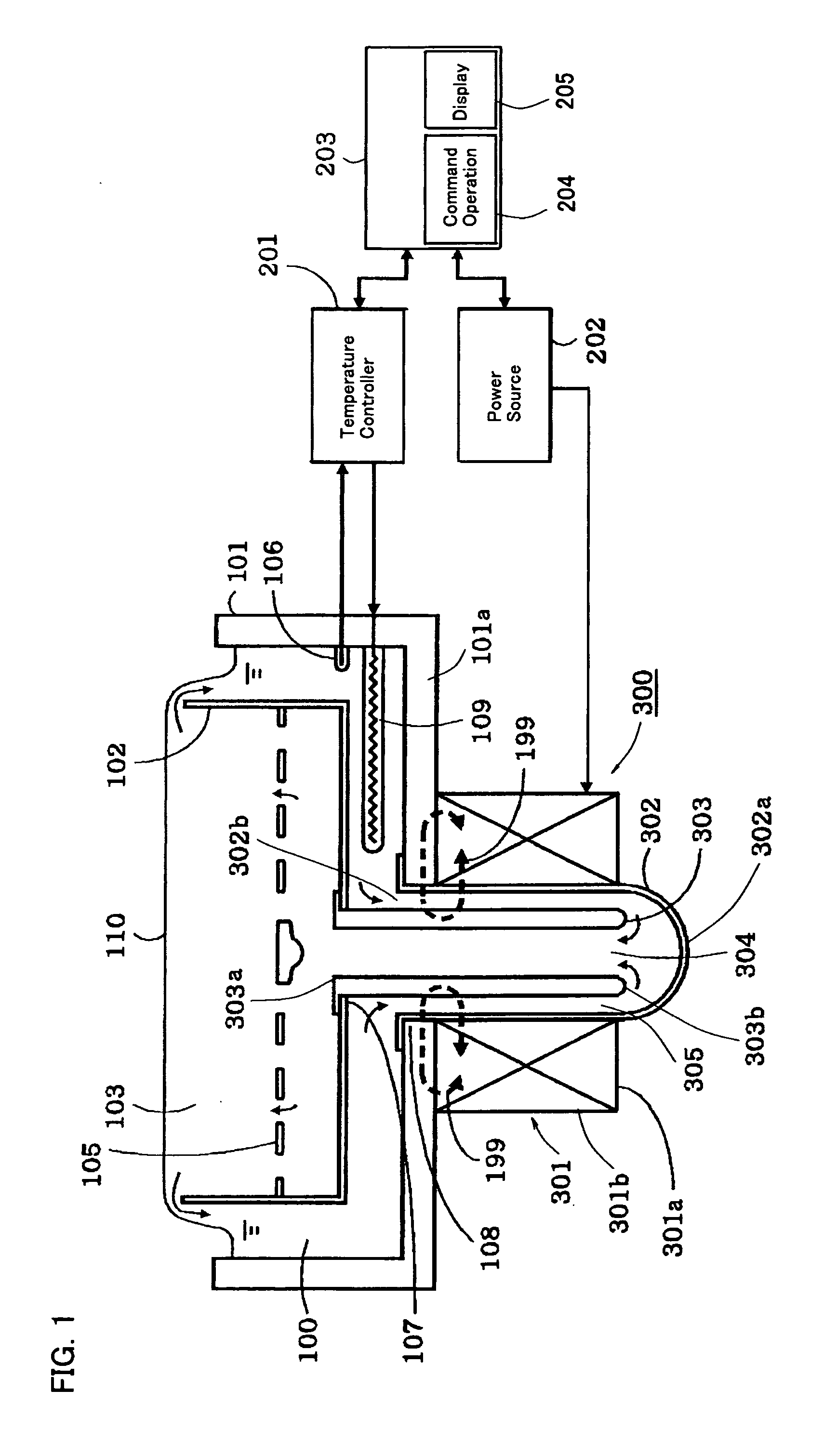
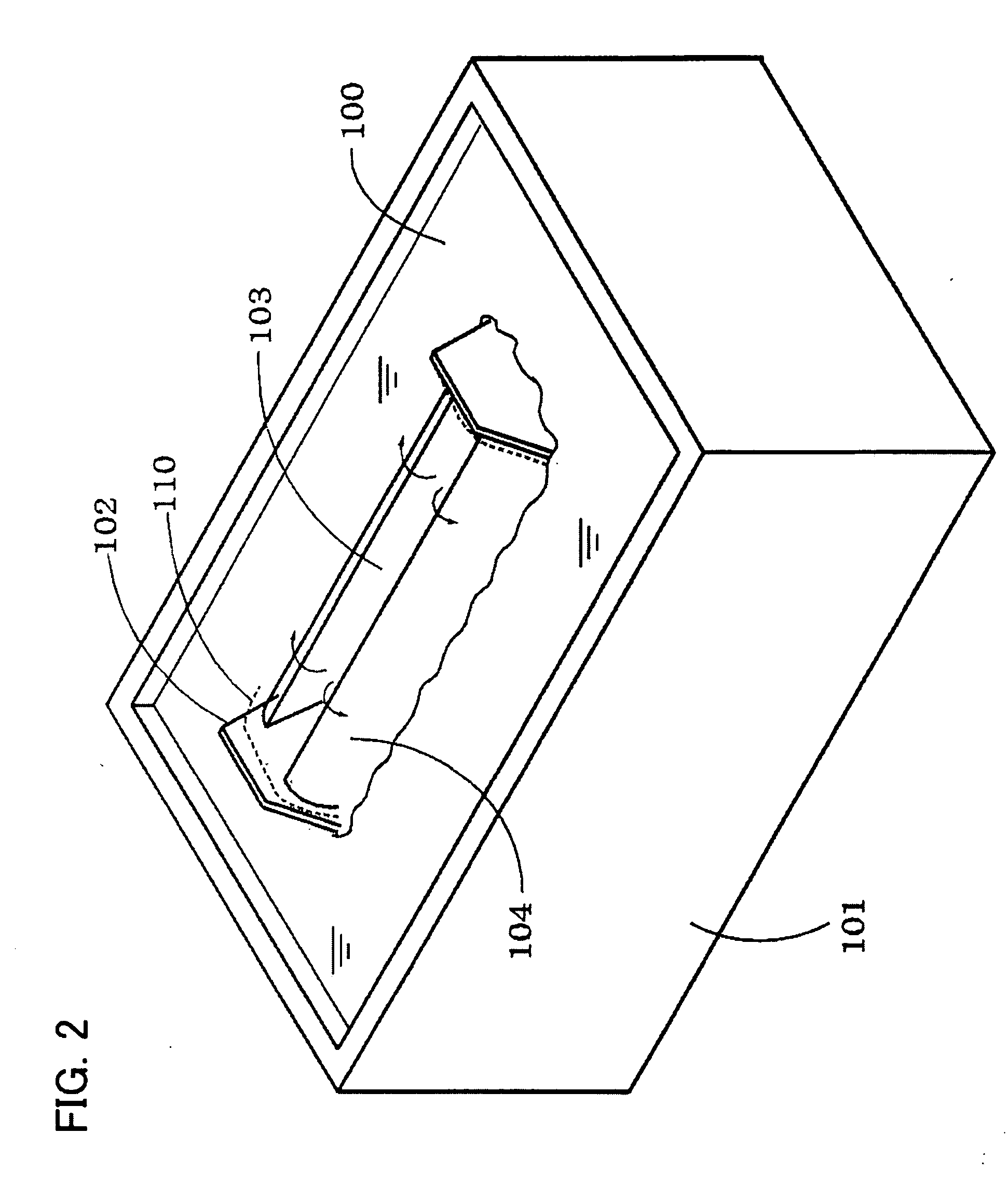
[0064]FIG. 1 depicts a solder vessel 101 shown in a vertical cross-sectional view and a control system shown in a block diagram. The solder vessel 101 has vessel walls including a bottom wall 101a along which a heater 109 for melting a solder 100 in the solder vessel 101 and maintaining the molten solder 100 at a desired temperature is disposed.

[0065] Designated as 201 is a temperature control device for controlling the temperature of the solder 100 in the solder vessel 101. The temperature control device 201 controls the temperature of the solder 100 at a desired value by controlling the supply of electric power to the heater 109 based on the result of detection by the temperature sensor 106.

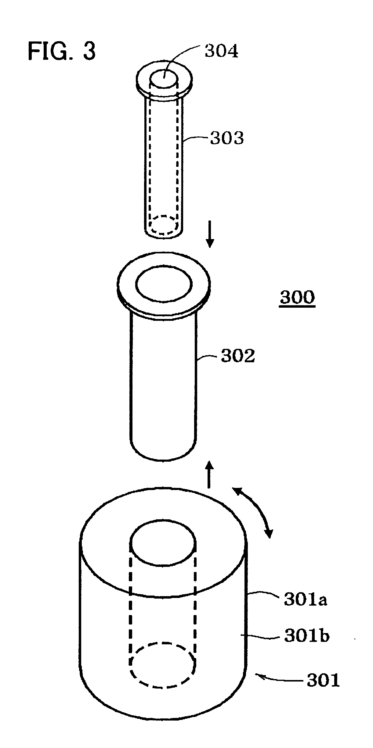
[0066] The bottom wall 101a of the solder vessel 101 is provided with a hole 108, to which a linear pipe 302 for an ALIP type electroma...

second embodiment

[0094] Description will be hereinafter made of a soldering apparatus according to a second embodiment of the present invention with reference to FIG. 5.

[0095]FIG. 5 is a view illustrating an example of the configuration of a soldering apparatus according to the second embodiment of the present invention, in which a solder vessel 101 is shown in a vertical cross-sectional view, and a control system is shown in a block diagram. The component parts corresponding to those in FIG. 1 are designated by the same reference numerals, and their description will not be repeated here. The difference between this embodiment and the first embodiment shown in FIG. 1 is that the bottom wall 101a of the solder vessel 101 has a recess 111 for receiving the drive means 301 (the outer core 301a and the coils 301b ) to increase the capacity of the solder vessel 101 without increasing the maximum dimensions of the soldering apparatus.

[0096] In this configuration, since heat loss from the electromagnetic...

third embodiment

[0099] The soldering apparatus disclosed in JP-A-2005-205479 has a heater for heating the solder in the solder vessel, a temperature sensor, and a temperature controlling device to melt the solder in the solder vessel and maintain the molten solder at a desired temperature. However, since the ALIP type electromagnetic pump is located outside the walls of the solder vessel and since solders have a high heat of fusion, it takes a long time until the solder in the linear pipe of the electromagnetic pump is melted completely after the solder in the solder vessel has been melted.

[0100] Therefore, it takes a long time until a projected wave can be formed after the start of the soldering apparatus.

[0101] The soldering apparatus disclosed in JP-A-2005-205479 is provided with a cap for closing the injection port of the nozzle so that induction heating of the solder in the linear pipe can be performed with the injection port of the nozzle closed with the cap. The induction heating is perfor...


PUM


Abstract

An R-ALIP type electromagnetic pump having an inner core, a linear pipe, and a combination of an outer core and coils provided around the linear pipe is disposed outside a solder vessel containing a molten solder. The solder vessel has a bottom wall made of an iron having at least 100 times as high a magnetic permeability as that of the molten solder and having a magnetic permeability not less than that of the inner core and a wall thickness not less than that of the inner core so that a magnetic field from the R-ALIP type electromagnetic pump cannot leak into the solder. Therefore, a stray current derived from an alternating magnetic field can be prevented from spreading in the molten solder.

Description

CROSS-REFERENCE TO RELATED APPLICATION [0001] This application claims, under 35 USC 119, priorities of Japanese Patent Applications No. 2005-282012, No. 2005-282013 and No. 2005-282015, all filed Sep. 28, 2005, disclosures of which, inclusive of the specifications, claims and drawings, are hereby incorporated by reference herein. BACKGROUND OF THE INVENTION [0002] 1. Field of the Invention [0003] The present invention relates to a soldering apparatus for soldering a printed wiring board having electronic parts mounted thereon. [0004] 2. Description of Prior Art [0005] Linear electromagnetic pumps (LEP), which directly apply an electromagnetic force to a medium to be transported to generate a thrust therein and use the thrust as a delivery force and a suction force, are roughly divided into two types: induction type and conduction type. In general, induction type pumps, which do not require passage of electric current through the medium to be transported, are widely used. [0006] Indu...

Claims


Application Information

Patent Timeline
IPC IPC(8): A47J36/02
CPCB23K3/06
Inventor TOBA, HIDEAKI
Owner NIHON DEN NETSU KEIKI CO LTD
Why Eureka
Try Eureka