
Lamp Base for a High-Pressure Discharge Lamp and Corresponding High-Pressure Discharge Lamp

a technology of high-pressure discharge and lamp base, which is applied in the direction of gas-filled discharge tubes, gaseous cathodes, lighting and heating apparatus, etc., can solve the problems of impeded lamp current change, low energy storage capacity, and comparatively high current flow

Inactive Publication Date: 2008-06-26
OSRAM GMBH
View PDF5 Cites 5 Cited by
  • Summary
  • Abstract
  • Description
  • Claims
  • Application Information

AI Technical Summary

Benefits of technology

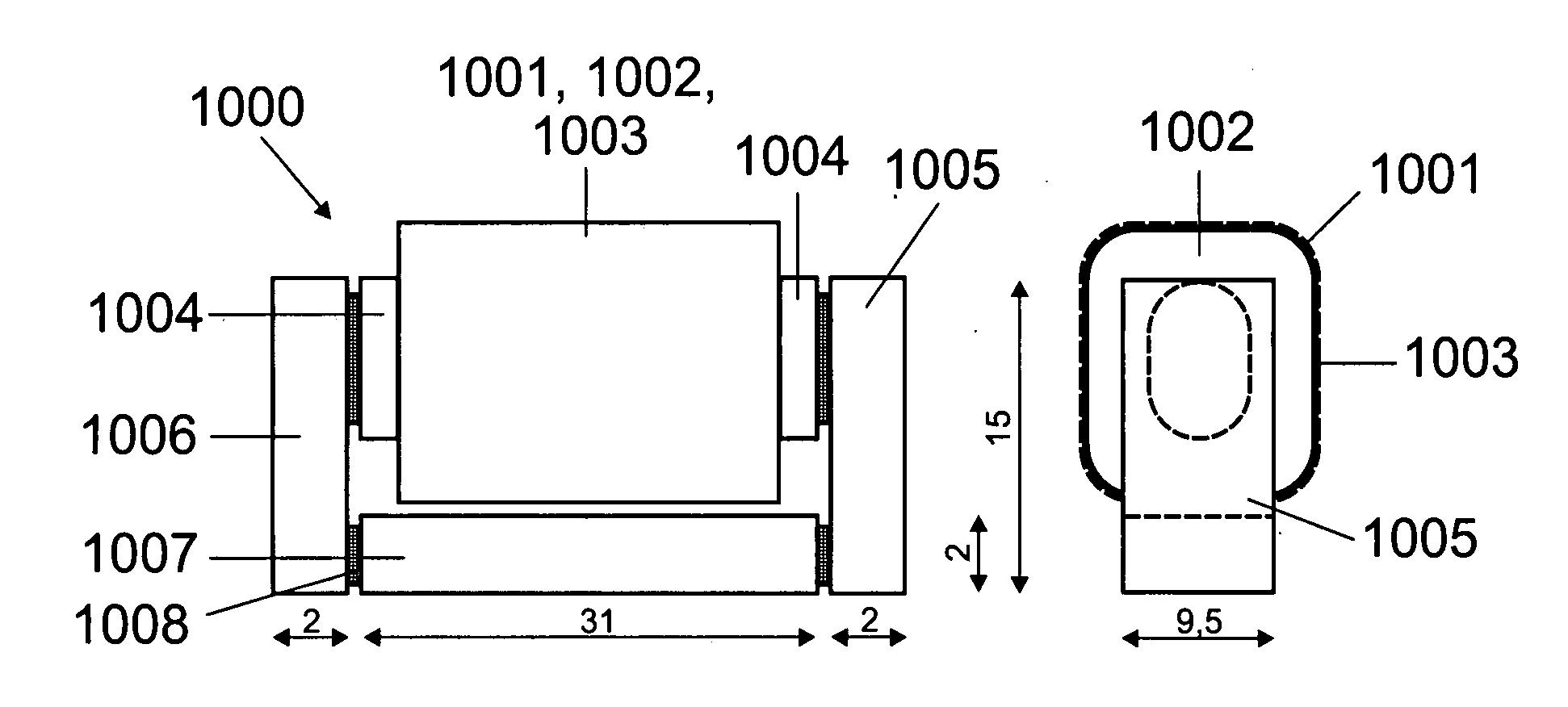
[0007]The at least two-part embodiment of the ignition transformer core ensures that the transformer core has at least one gap and therefore does not have the abovementioned disadvantages of the toroidal-core transformer in accordance with the prior art cited above. In particular, the secondary winding of the ignition transformer arranged in the lamp base according to the invention can therefore ensure sufficient limitation of the lamp current immediately after the ignition of the gas discharge in the high-pressure discharge lamp and can prevent an undesirably high rise in the lamp current. In addition, the cylindrical section of the first core component allows for a precise design and arrangement of the transformer windings either directly on the first core component or on a coil former, which surrounds the cylindrical section of the first core component. The formation of the at least two core components such that the at least one second core component bridges that section of the first core component which is provided with the windings and produces a magnetic return path from a first end of the first core component to a second end of the first core component (1004) reduces the leakage field of the ignition transformer considerably because the magnetic lines of force run virtually entirely in the core components consisting of ferromagnetic and ferrimagnetic material. This ignition transformer therefore does not induce any notable currents in a metallic shielding housing of the lamp base, which serves the purpose of improving the electromagnetic compatibility, and therefore does not have the disadvantages of the lamp base equipped with a rod-core transformer in accordance with the prior art cited above.
[0011]The at least one gap between the core components of the ignition transformer advantageously has a width of less than or equal to 4 mm in order to keep the leakage field of the transformer small.
[0012]In order to make it possible to manufacture the ignition transformer in a simple manner and to make contact with the transformer windings in a simple manner with a physical separation of the high-voltage-conducting connection of the secondary winding, the secondary winding and the primary winding are preferably arranged one over the other, the secondary winding being arranged so as to lie on the inside, and the primary winding being arranged so as to lie on the outside. Preferably, the secondary winding is either wound directly onto the cylindrical section of the first core component or onto a coil former, which surrounds the abovementioned section of the first core component. The primary winding is preferably arranged over the secondary winding in such a way that it is separated by electrical insulation.
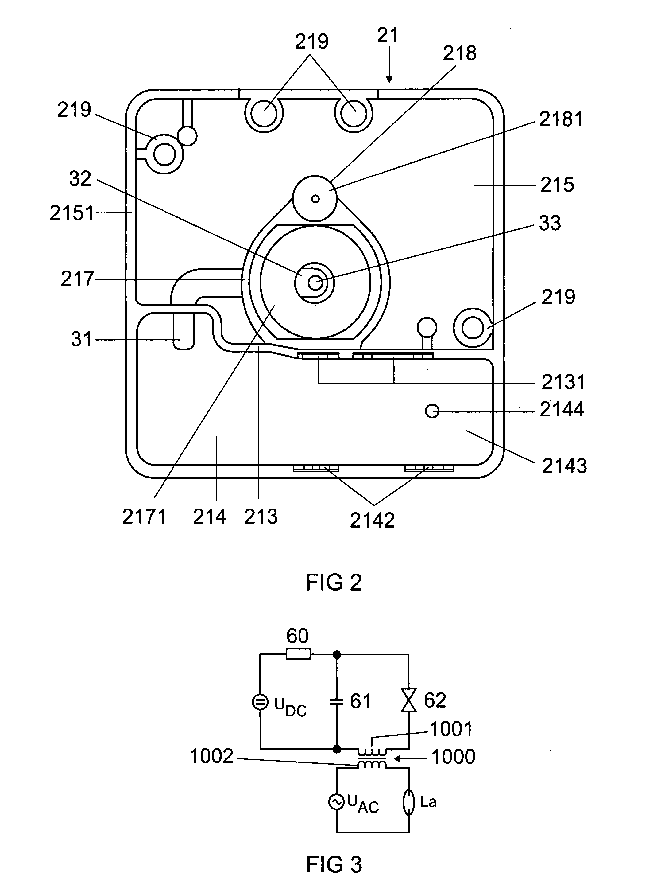
[0013]Preferably, a complete pulse ignition apparatus for the high-pressure discharge lamp is accommodated in the lamp base according to the invention. This pulse ignition apparatus comprises, in addition to the ignition transformer, also a spark gap or a threshold value element, via which the ignition capacitor is discharged when the breakdown voltage is exceeded. The breakdown voltage of the spark gap or of the threshold value element is advantageously in the range of from 400 V to 1500 V, and the turns ratio of the transformer windings is advantageously in the range of from 10 to 80. This ensures that, on the one hand, sufficiently high ignition voltage pulses of up to 30 kV can be generated with the aid of the pulse ignition apparatus and, on the other hand, no excessive power losses occur during lamp operation after the starting phase in the secondary winding, through which the lamp current flows. Preferably, the secondary winding of the ignition transformer is also designed for this purpose such that its DC resistance is less than 1 ohm.
[0015]The abovementioned holding means for the at least one second core component preferably comprise a snap-action or latching mechanism. As a result, the at least one second core component can be fixed in a simple manner in the predetermined position and orientation with respect to the first core component.
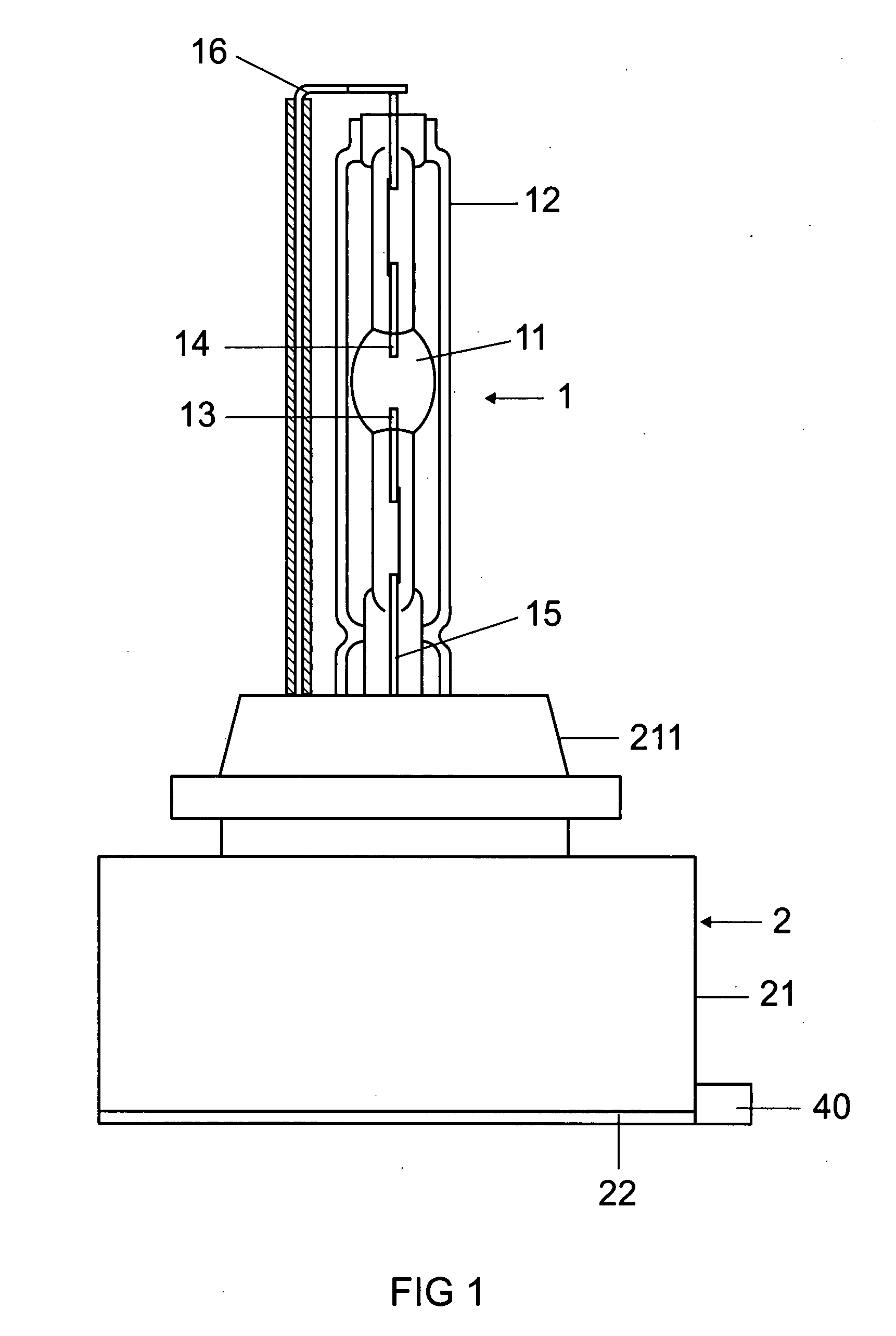
[0016]In accordance with a further exemplary embodiment of the invention, the at least one second core component of the ignition transformer is arranged in a cavity of the lamp base, with the result that the individual components of the ignition transformer are therefore fitted only when it is inserted in the lamp base. Preferably, the abovementioned cavity for the at least one second core component is located in one or more walls of the lamp base, which walls form a chamber for the ignition transformer or for the first core component of the ignition transformer with the windings arranged thereon. The at least one second core component of the transformer is therefore formed as part of the lamp base or the chamber wall, and the thus equipped walls of the chamber ensure optimum limitation of the magnetic leakage field of the ignition transformer once the first core component has been inserted in the chamber. Alternatively, the at least one second core component can be fixed in the abovementioned chamber by holding means, which are fitted to the lamp base. These holding means preferably comprise a snap-action or latching mechanism.

Problems solved by technology

An ignition transformer having a closed core has the disadvantage that, owing to its high inductance during lamp operation after the end of the ignition phase, it impedes the change in polarity of the lamp current if the high-pressure discharge lamp is operated with a current of alternating polarity and the lamp current flows through the secondary winding of the ignition transformer.
In addition, with such an ignition transformer the saturation state is reached quickly, with the result that it has a comparatively low energy storage capacity and, after the end of the ignition phase of the high-pressure discharge lamp, a comparatively high current flow occurs which can overload the electrical components of the operating device of the lamp since the inductor effect of the secondary winding of such an ignition transformer is comparatively low.
In addition, the application of the transformer windings on to a toroidal core is complex.

Method used


Image

  • Lamp Base for a High-Pressure Discharge Lamp and Corresponding High-Pressure Discharge Lamp
  • Lamp Base for a High-Pressure Discharge Lamp and Corresponding High-Pressure Discharge Lamp
  • Lamp Base for a High-Pressure Discharge Lamp and Corresponding High-Pressure Discharge Lamp

Examples


Embodiment Construction

[0004]The object of the invention is to provide a lamp base for a high-pressure discharge lamp which avoids the above-mentioned disadvantages of the prior art.

[0005]This object is achieved according to the invention by the features of patent claim 1. Particularly advantageous embodiments of the invention are described in the dependent patent claims.

[0006]The lamp base according to the invention for a high-pressure discharge lamp has an ignition transformer, which is arranged in the interior of the lamp base, for igniting the gas discharge in the high-pressure discharge lamp, the core of the ignition transformer being formed by a first core component and at least one second core component, which each consist of a ferromagnetic or ferrimagnetic material and are separated by at least one gap, the first core component having a cylindrical section, on which the windings of the ignition transformer are arranged, and the core components being designed such that the at least one second core...


PUM


Abstract

A lamp base (2) for a high-pressure discharge lamp comprises an ignition transformer (1000), which is placed in the interior (214) of the lamp base (2) and which serves to ignite the gas discharge inside the high-pressure discharge lamp. To this end, the ignition transformer (1000) comprises a core on which its windings (1001, 1002) are placed. The core is formed by a first core part (1004) and by at least one second core part (1005, 1006, 1007), which are each made of a ferromagnetic or ferrimagnetic material and are separated by at least one gap (10078). The first core part (1004) has a cylindrical section on which the windings (1001, 1002) of the ignition transformer (1000) are placed, and core parts (1004, 1005, 1006, 1007) are formed in such a manner that the core, apart from the at least one gap (1008), has a closed shape.

Description

[0001]The invention relates to a lamp base for a high-pressure discharge lamp in accordance with the precharacterizing clause of patent claim 1 and to a high-pressure discharge lamp.I. PRIOR ART[0002]Such a lamp base has been disclosed, for example, in WO 97 / 35336. This document describes a lamp base for a high-pressure discharge lamp having an ignition transformer, which is arranged in the interior of the lamp base and has a closed core. In particular, the ignition transformer is in the form of a toroidal-core transformer. An ignition transformer having a closed core has the disadvantage that, owing to its high inductance during lamp operation after the end of the ignition phase, it impedes the change in polarity of the lamp current if the high-pressure discharge lamp is operated with a current of alternating polarity and the lamp current flows through the secondary winding of the ignition transformer. In addition, with such an ignition transformer the saturation state is reached q...

Claims


Application Information

Patent Timeline
IPC IPC(8): H05B41/04F21Y101/00
CPCH01F27/255H05B41/042H01F38/10
Inventor LERCHEGGER, DANIELSIESSEGGER, BERNHARD
Owner OSRAM GMBH
Learn More