
Wiper blade

A technology of wiper blades and wiper strips, which is applied in vehicle cleaning, vehicle maintenance, transportation and packaging, etc., can solve the problems of expensive manufacturing process and weakening, and achieve the effects of avoiding weakening, effortless assembly and improving stability

Inactive Publication Date: 2009-07-01
ROBERT BOSCH GMBH
View PDF6 Cites 2 Cited by
  • Summary
  • Abstract
  • Description
  • Claims
  • Application Information

AI Technical Summary

Problems solved by technology

However, for this it is necessary to add or punch out grooves at the connecting device on the bracket, which will weaken the bracket at this highly sensitive point
In addition, another process step is necessary here, which makes the production process expensive

Method used


Image

  • Wiper blade
  • Wiper blade
  • Wiper blade

Examples


Embodiment Construction

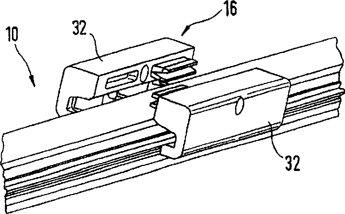
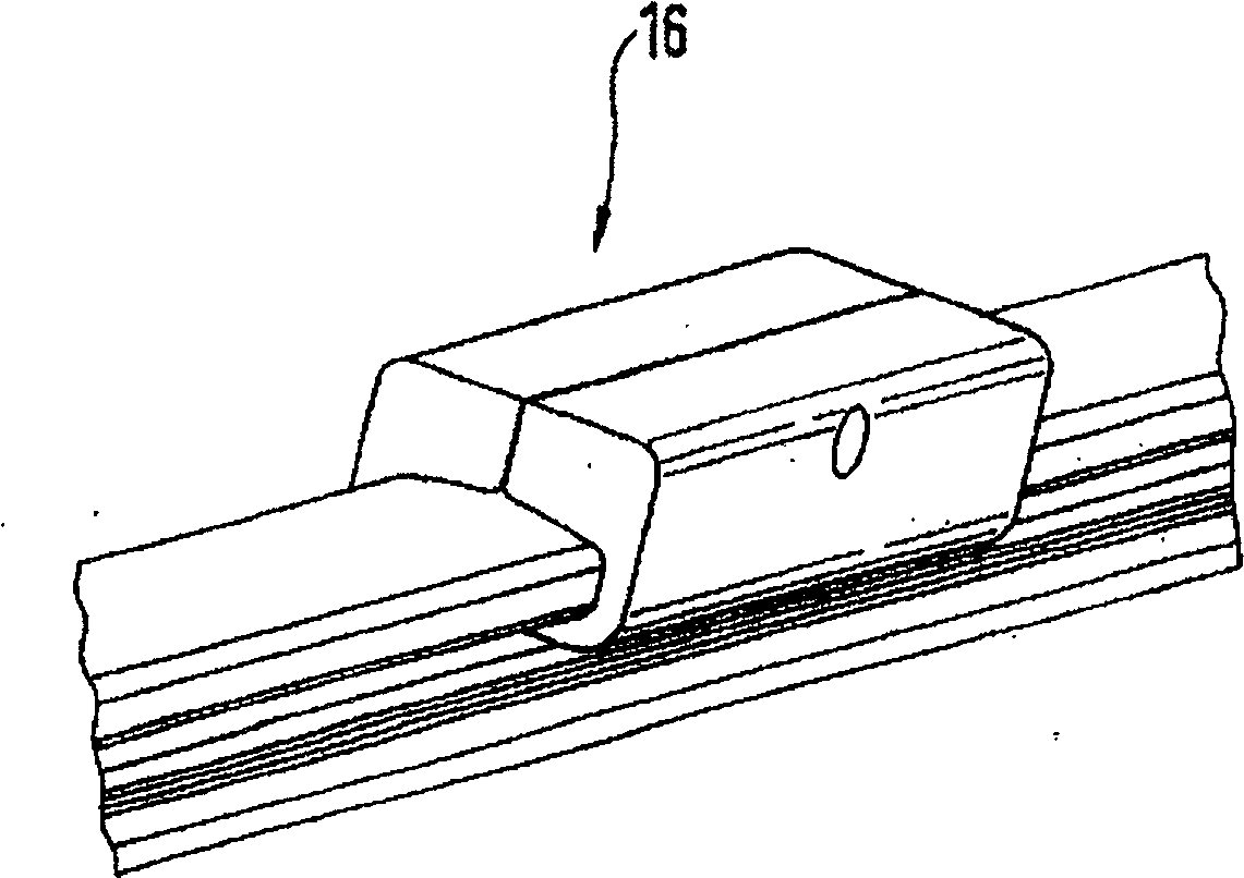
[0027] exist Figure 15 shows a wiper blade 10 according to the invention, it has a wiper strip 12, a bracket 14, the bracket is for example in Figure 5 The wiper blade also has a connecting device 16 for connecting a wiper arm 18 via a hinge shaft, as shown in a sectional view in FIG. By means of the wiper arm 18 the wiper blade 10 can be guided on the glass 22 to be wiped, the glass Figure 15 Indicated by dotted lines. exist Figure 15 The middle wiper blade 10 has not yet been completely erected on the glass 22 , and only the end 24 of the wiper blade bears against the glass 22 when the wiper strip 12 is still at a distance from the glass 22 at the connecting device 16 . The wiper strip 12 is pressed against the glass 22 by the clamping force of the bracket 14 when a predetermined contact pressure is exerted on the connecting device 16 via the wiper arm 18 . This clamping force by the bracket 14 ensures a uniform contact pressure over the entire length of the wiper bl...


PUM


Abstract

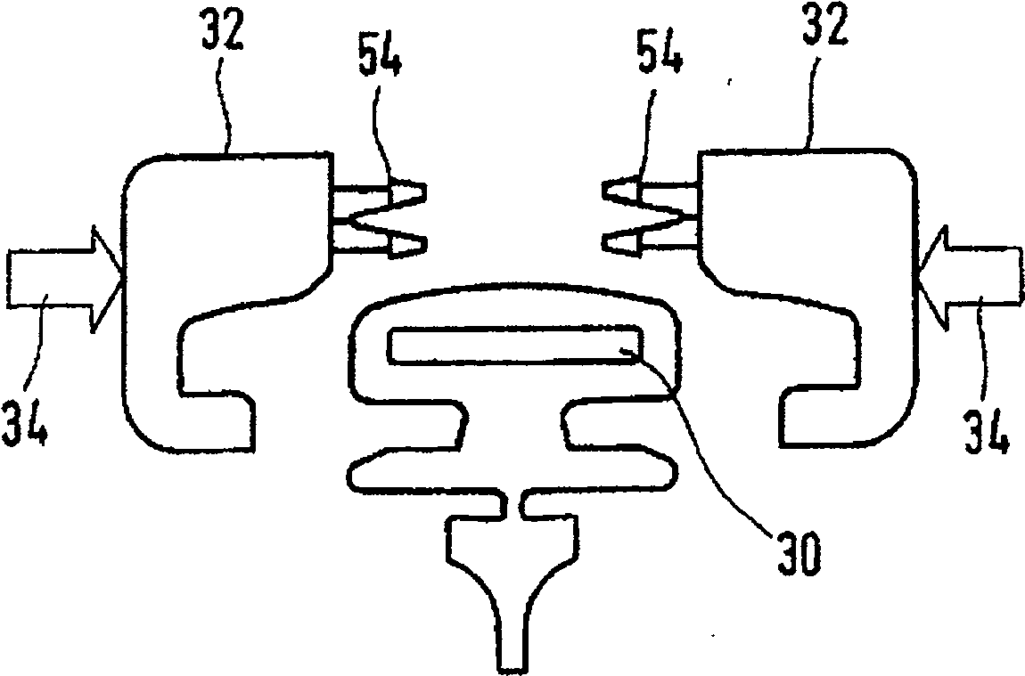
The wiper blade (10) comprises a wiping blade carried by an element and a fastening device (16) so as to be fixed to a wiper arm. The fastening device comprises fastening parts (32) able to move relative to each other. The fastening parts engage with the wipe blade material when they are connected to each other and realize a fixing locked in sliding between the fastening device and the wiper blade and between the wiper blade and carrying element.

Description

technical field [0001] The invention relates to a wiper blade for wiping automobile glass, which has a wiper strip, a bracket for the wiper strip and a connection device for connecting a wiper arm, wherein the connection device comprises a relatively movable and Interconnected connecting parts. Background technique [0002] A support ensures that the wiper blade top pressure from the wiper arm is distributed as evenly as possible on the glass over the entire wiper area wiped by the wiper blade. Due to the corresponding bending of the unloaded bracket, although the wiper blade does not bear against the glass, the end of the wiper strip which completely rests on the glass during wiper blade operation is loaded against the glass by the clamped bracket, despite the spherically curved The bending radius of the vehicle glass varies for each wiper blade position. The curvature of the wiper blade must also be slightly greater than the maximum curvature measured in the wiping area ...

Claims


Application Information

Patent Timeline
Patent Type & Authority Patents(China)
IPC IPC(8): B60S1/32B60S1/38B60S1/40
CPCB60S1/381B60S1/3877B60S1/40B60S1/386B60S1/3863
Inventor M·维勒J·齐默K·米尔普福特W·罗伊特施J·迪特里希J·-M·里特P·德布洛克
Owner ROBERT BOSCH GMBH
Learn More