Tool for connecting cable conductors

A technology for connecting cables and cable core wires, which is applied in the field of tools for connecting cable conductors, and can solve problems such as forgetting to reinstall safety connectors and inconsistent procedures

Inactive Publication Date: 2009-07-01
ADC GMBH
View PDF8 Cites 1 Cited by
  • Summary
  • Abstract
  • Description
  • Claims
  • Application Information

AI Technical Summary

Problems solved by technology

However, on the one hand, this means additional work for the installation engineer, and on the other hand, it does not correspond to the procedures required from safety considerations
Moreover, the reinstallation of the safety connector may be forgotten
When the space conditions on the terminal strip are reduced, the optimization of the tools for connecting the cable cores to the insulating piercing contact elements creates problems, which have hitherto not been satisfactorily solved by conventional methods and devices known in the prior art the solution

Method used


Image

  • Tool for connecting cable conductors
  • Tool for connecting cable conductors
  • Tool for connecting cable conductors

Examples


Embodiment Construction

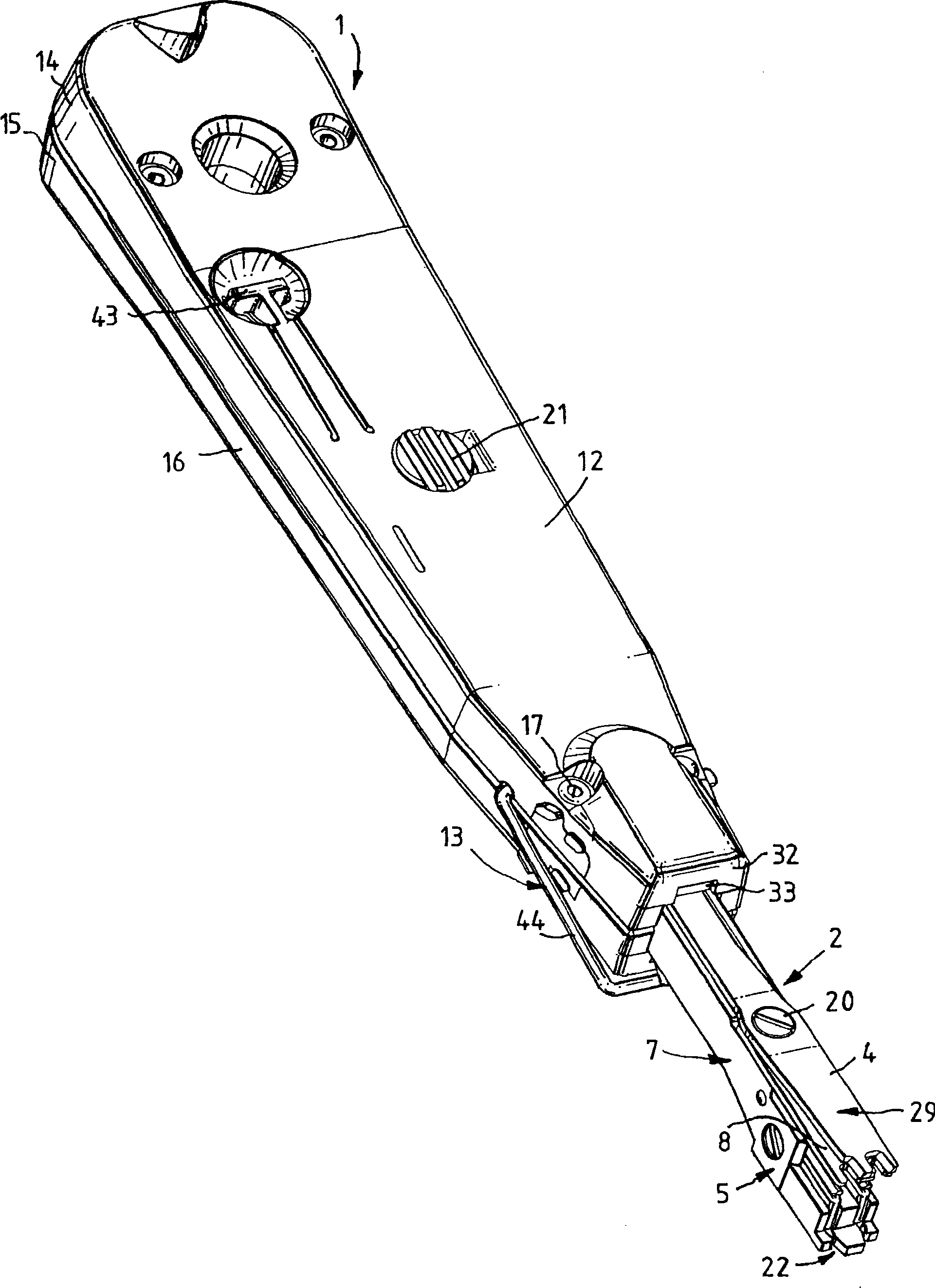
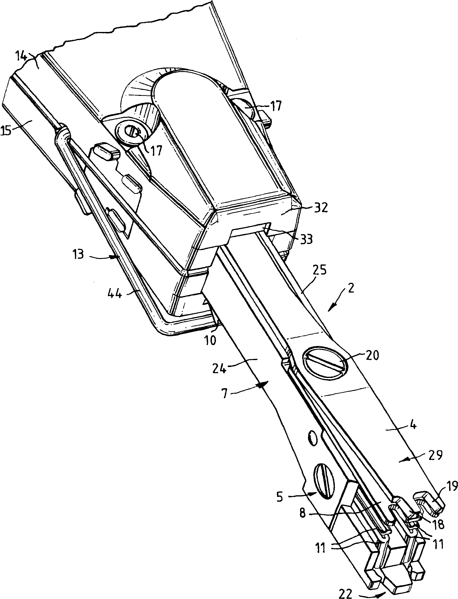
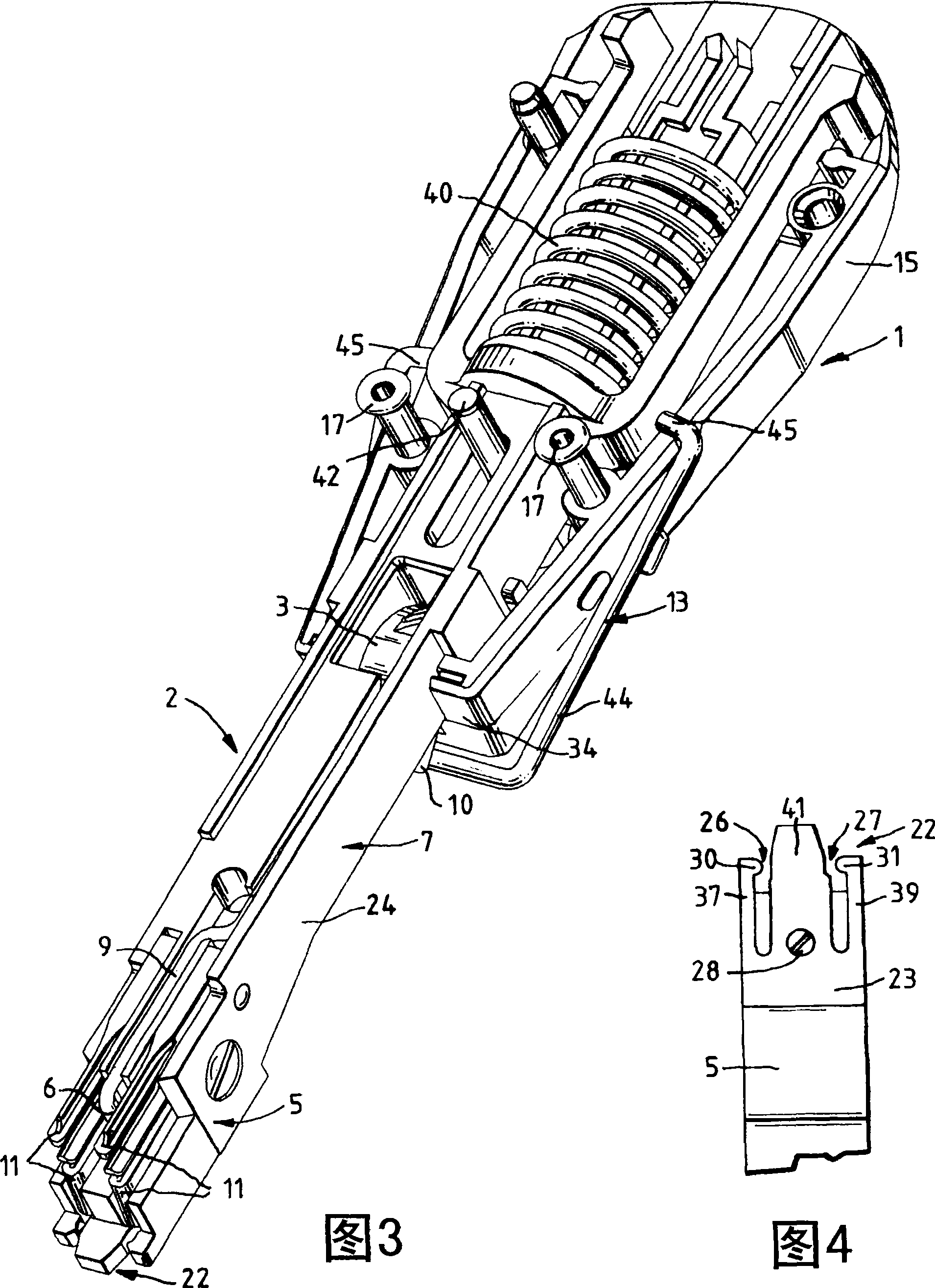
[0035] figure 1 A tool 1 is shown comprising a tool housing 12 consisting of two plastic half-shells 14 , 15 and forming a clamp 16 . The two housing half-shells 14 , 15 are connected to each other by screws 17 . The longitudinally movable ram 2 is arranged in the clamp 16 provided with an opening 33 on one end face 32 , the ram has a striking mechanism and protrudes from the opening 33 in the end face 32 of the tool housing 12 . The part of the ram 2 protruding from the tool 1 includes a ram tool holder 5 located at the front end of the ram 2 and a ram handle 7 located between the ram tool holder 5 and the opening 33 of the tool housing. A cutter 29 for cutting the cable core is arranged on the ram knife holder, and the longitudinal displacement of the ram 2 is used to trigger the cutting operation. The cutter 29 in this case comprises two shearing blades 4, 8 which are relatively movable and which are laid flat one above the other on the ram tool holder 5, the inner sheari...


PUM


Abstract

The invention relates to a tool for connecting cable cores, in particular of insulated telecommunication and data cables, to an insulation-piercing contact element, with a ram, which is formed with a ram head, by means of which the cable cores can be pressed into the insulation-piercing contact, the ram head being shaped in such a way that at least two cable cores can be pressed in simultaneously into at least two insulation-piercing contact elements lying next to each other.

Description

technical field [0001] The invention relates to a tool for connecting cable cores, in particular insulated telecommunication and data synchronization transmission cables, with insulated perforated contact elements. Background technique [0002] EP0040307B1 discloses a tool for connecting insulated electrical conductors. The tool consists of a hollow double-shell clamp in which is arranged a striking mechanism with a spring-loaded hollow slide and a ram capable of moving longitudinally against the force of the spring. A wire cutter is arranged on the ram portion extending from the front end of the ram head on the jig, the wire cutter includes two shearing legs, one pivotable and located at the rear inside the jig The end has an inclined longitudinal slot in which a pin fastened to the clamp is guided. Thus, longitudinal movement of the ram results in pivoting of the movable shearing leg. In order to connect the insulated cable cores to the insulating perforated contact ele...

Claims


Application Information

Patent Timeline
Patent Type & Authority Patents(China)
IPC IPC(8): H01R43/01
CPCY10T29/5193Y10T29/53217Y10T29/5151Y10T29/53222Y10T29/53226H01R43/015
Inventor 曼弗雷德·米勒海科·诺伊梅茨勒
Owner ADC GMBH
Why Eureka
Try Eureka