Multifunctional double arm interaction single-drive-wheel self-speed-changing pumping unit
A single-drive, self-variable technology, applied in the fields of production fluids, wellbore/well components, earth-moving drilling, etc., can solve the problems of high power consumption of pumping units, equipment damage to pumping oil, and low oil pumping rate of oil wells , to achieve the effect of easy start, overcoming equipment damage, and improving oil pumping rate
- Summary
- Abstract
- Description
- Claims
- Application Information
AI Technical Summary
Problems solved by technology
Method used
Image
Examples
Embodiment 1
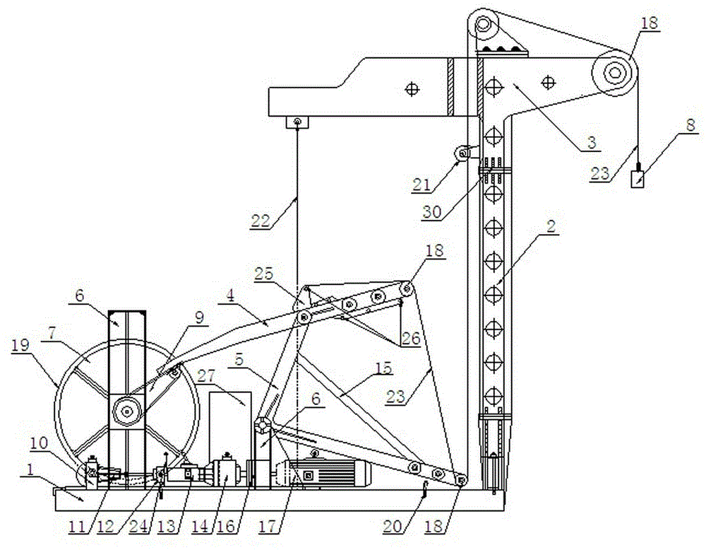
[0052] A multifunctional double-arm interactive single-drive wheel self-variable pumping unit, including a base 1, a column 2, a boom assembly 3, a motor 17, a speed change mechanism, a suspension rope 23, and a wellhead pumping device 8, and one end of the column 2 is fixed Installed on the base 1, the other end is fixedly connected with the boom assembly 3, the boom assembly 3 is provided with a fixed pulley 18, the speed change mechanism is connected with the power output end of the motor 17, and also includes a driving wheel 7, a torque arm 9, The first power arm 4 and the second power arm 5, the driving wheel 7 is connected with the speed change mechanism, the torque arm 9 is fixed on the driving wheel 7, and one end of the first power arm 4 is movably connected with the torque arm 9, The other end is provided with a fixed pulley 18 and a hanging rope fixing hole 26; one end of the second power arm 5 is movably connected with the first power arm 4, and the other end is pro...
Embodiment 2
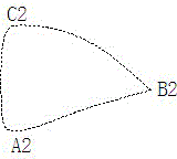
[0072] This embodiment is basically the same as the above-mentioned embodiment, the main difference is that the suspension rope 23 is preferably fixed under the side of the outermost fixed pulley 18 at the end of the first power arm 4, and the suspension rope 23 passes through the first power arm 4 and the second power arm 4 respectively. The fixed pulley 18 at the extreme end of the two power arms 5, such as image 3 As shown, the running distance of the upstroke is A1B1, the running distance of the downstroke is A1C1B1, A1B1 is 1 / 2 times of A1C1B1, that is, the running distance of the upstroke of the pumping unit is 1 / 2 times the running distance of the downstroke, this structure makes the upstroke The running speed of the stroke is 2 times that of the downstroke, even if the gap between the wellhead oil pumping device 8 and the oil pumping pipeline is larger due to wear and tear, oil can be extracted from the oil well, and it is suitable for late oil well pumping.
Embodiment 3
[0074] This embodiment is basically the same as the above-mentioned embodiment, and the main difference is that the hanging rope 23 is preferably fixed on the hanging rope fixing hole 26 of the boss 25 above the first power arm 4 and the hanging rope below the side of the outermost fixed pulley 18 of the first power arm 4 . In any hanging rope fixing hole 26 between the rope fixing holes 26, the hanging rope 23 respectively passes through any fixed pulley 18 on the first power arm 4 and the second power arm 5, as Figure 4 As shown, the running distance of the upstroke is A1B1, and the running distance of the downstroke is A1C1B1, that is, the running distance of the upstroke is 0.5-1 times the running distance of the downstroke, and the fixed position of the suspension rope 23 can be adjusted according to the change of the oil volume in the oil well , the upstroke running speed of the pumping unit is 1-2 times of the downstroke running speed, which is suitable for mid-term oil...
PUM
 Abstract
Description
Claims
Application Information
 - R&D
- Intellectual Property
- Life Sciences
- Materials
- Tech Scout
- Unparalleled Data Quality
- Higher Quality Content
- 60% Fewer Hallucinations
Browse by: Latest US Patents, China's latest patents, Technical Efficacy Thesaurus, Application Domain, Technology Topic, Popular Technical Reports.
© 2025 PatSnap. All rights reserved.Legal|Privacy policy|Modern Slavery Act Transparency Statement|Sitemap|About US| Contact US: help@patsnap.com


