Multifunctional double arm interaction double-drive-wheel self-speed-changing pumping unit

A dual-drive wheel, multi-functional technology, applied in the direction of production fluid, wellbore/well parts, earthwork drilling and production, etc., can solve problems such as crash, motor equipment shutdown, low oil well pumping rate, etc., to prolong service life, move Consistent speed and improved pumping efficiency

Active Publication Date: 2015-06-24
德阳振华机械设备制造有限公司
View PDF8 Cites 0 Cited by
  • Summary
  • Abstract
  • Description
  • Claims
  • Application Information

AI Technical Summary

Problems solved by technology

[0007] 1. Due to the very large friction between the wellhead pumping device and the oil pumping pipeline, there is a gap between the wellhead pumping device and the pipeline. Long-term use causes the gap to gradually increase, while the pumping unit in the prior art is pumping oil upwards The speed in the process is constant, which causes some of the oil pumped each time to flow out from the gap. With the gradual increase of the gap, the pumping unit not only pumps less oil each time, but also from new oil wells to In the middle or late oil well, the oil cannot even be pumped out from the oil well, and the oil pumping rate of the oil well is low. , to move the counterweight from the lowest point to the highest point of its motion track, a high-power motor is needed to start, so it is difficult to start the beam pumping unit, but when the beam pumping unit is started, it only needs Half of the power of the high-power motor can maintain the pumping operation, resulting in high power consumption of the pumping unit; 3. When the counterweight moves from the highest point to the lowest point of its trajectory, due to the weight of the counterweight is very heavy, the following The punching speed will be very fast. When the downstroke speed of the counterweight is greater than the speed of the motor, the potential energy in the downstroke process will be converted into electric energy, thereby generating a large pulse current, which will cause serious distortion of the power grid and cause motor equipment. Large-scale shutdown and crash, that is, the so-called "shock electricity" phenomenon, which leads to equipment damage and oil pumping stop; 4. At present, when the beam pumping unit is in operation, it is necessary to refuel the main box to increase lubricity , but after refueling, the gearbox is prone to oil leakage, and there is a big safety hazard in the oil pumping process; 5. The overall weight of the beam pumping unit is very heavy, and the amount of steel consumed is large. Purchasing the pumping unit Sixth, when the sling runs on the downward stroke, there is no oil load on the sling at this time, and the crank is only subjected to the self-weight impact of the beam and the donkey head. Therefore, during the oil pumping process, the impact force received by the crank is uneven and changes at any time, which will easily lead to damage to the crank, which not only affects the service life of the equipment, but also seriously causes safety problems. Accident, and the crank is damaged, it is difficult to repair, and if the parts are replaced, it will be more expensive

Method used


Image

  • Multifunctional double arm interaction double-drive-wheel self-speed-changing pumping unit
  • Multifunctional double arm interaction double-drive-wheel self-speed-changing pumping unit
  • Multifunctional double arm interaction double-drive-wheel self-speed-changing pumping unit

Examples


Embodiment 1

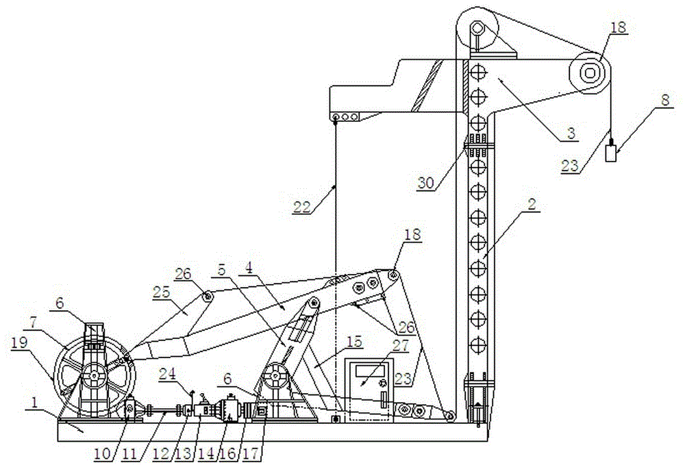
[0050] A multi-functional double-arm interactive double-drive wheel self-variable pumping unit, including a base 1, a column 2, a boom assembly 3, a motor 17, a speed change mechanism, a suspension rope 23, and a wellhead pumping device 8, and one end of the column 2 is fixed Installed on the base 1, the other end is fixedly connected with the boom assembly 3, the boom assembly 3 is provided with a fixed pulley 18, the speed change mechanism is connected with the power output end of the motor 17, and also includes two driving wheels 7, the first The power arm 4 and the second power arm 5, the speed change mechanism is connected with two driving wheels 7, one end of the first power arm 4 is located between the two driving wheels 7 and is movably connected with the two driving wheels 7, and the other One end is provided with a fixed pulley 18 and a suspension rope fixing hole 26; one end of the second power arm 5 is movably connected with the first power arm 4, and the other end ...

Embodiment 2

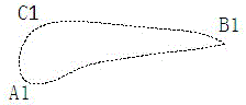
[0069] This embodiment is basically the same as the above-mentioned embodiment, the main difference is that the suspension rope 23 is preferably fixed under the side of the outermost fixed pulley 18 at the end of the first power arm 4, and the suspension rope 23 passes through the first power arm 4 and the second power arm 4 respectively. The fixed pulley 18 at the extreme end of the two power arms 5, such as image 3 As shown, the running distance of the upstroke is A1B1, the running distance of the downstroke is A1C1B1, A1B1 is 1 / 2 times of A1C1B1, that is, the running distance of the upstroke of the pumping unit is 1 / 2 times the running distance of the downstroke, this structure makes the upstroke The running speed of the stroke is 2 times that of the downstroke, even if the gap between the wellhead oil pumping device 8 and the oil pumping pipeline is larger due to wear and tear, oil can be extracted from the oil well, and it is suitable for late oil well pumping.

Embodiment 3

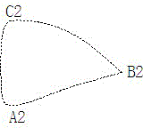
[0071] This embodiment is basically the same as the above-mentioned embodiment, and the main difference is that the hanging rope 23 is preferably fixed on the hanging rope fixing hole 26 of the boss 25 above the first power arm 4 and the hanging rope below the side of the outermost fixed pulley 18 of the first power arm 4 . In any hanging rope fixing hole 26 between the rope fixing holes 26, the hanging rope 23 respectively passes through any fixed pulley 18 on the first power arm 4 and the second power arm 5, as Figure 4 As shown, the running distance of the upstroke is A1B1, and the running distance of the downstroke is A1C1B1, that is, the running distance of the upstroke is 0.5-1 times the running distance of the downstroke, and the fixed position of the suspension rope 23 can be adjusted according to the change of the oil volume in the oil well , the upstroke running speed of the pumping unit is 1-2 times of the downstroke running speed, which is suitable for mid-term oil...


PUM


Abstract

The invention discloses a multifunctional double arm interaction double-drive-wheel self-speed-changing pumping unit which comprises a lifting arm assembly, a lifting rope, a wellhead pumping unit, two drive wheels, a first power arm and a second power arm. The drive wheels are connected with a speed change mechanism. One end of the first power arm is located between the two drive wheels and movably connected with the same while the other end of the first power arm is provided with a fixed pulley and a lifting rope fixing hole. One end of the second power arm is movably connected with the first power arm while the other end of the second power arm is provided with a fixed pulley. The second power arm is provided with a base point. The second power arm reciprocates around the base point. One end of the lifting rope is fixedly connected with the wellhead pumping device through a fixed pulley on the lifting arm assembly. The other end of the lifting rope is fixed in the lifting rope fixing hole on the first power arm sequentially through the fixed pulley on the second power arm and the fixed pulley on the first power arm. By the pumping unit, stroke frequency can be adjusted conveniently, upstroke speed is increased, pumping efficiency is improved, and more oil can be pumped out of oil wells.

Description

technical field [0001] The invention relates to the technical field of oil production machinery, in particular to a multifunctional double-arm interactive double-drive wheel self-variable oil pumping unit, which is mainly suitable for 6m stroke. Background technique [0002] In oil extraction, beam pumping units are mainly used to extract oil from oil wells. At present, the conventional beam pumping unit generally consists of a rope hanger, a donkey head, a beam, a frame, a connecting rod, a reducer, a crank, a balance device, a base, a frame, and a motor. The beam beam machine has the disadvantages of short stroke, small displacement, large volume, heavy weight, and high energy consumption. The most important problem is the distortion of the power grid caused by self-generated electricity. [0003] In order to solve the above problems, the following patented technologies have been proposed in the prior art: [0004] For example, Chinese Patent No. "201120146696.0" disclos...

Claims


Application Information

Patent Timeline
Patent Type & Authority Patents(China)
IPC IPC(8): E21B43/00
Inventor 李兆胜
Owner 德阳振华机械设备制造有限公司
Why Eureka
Try Eureka