Beam-pumping unit

A technology of pumping unit and pumping mechanism, which is applied in the direction of mechanical equipment, machine/engine, liquid displacement machinery, etc., and can solve the problems of small reciprocating stroke of sucker rod, high manufacturing and operating costs, and low oil pumping efficiency , to achieve the effect of improving oil pumping rate, low operating cost and saving electric energy

Inactive Publication Date: 2005-06-08
郑常海
View PDF0 Cites 0 Cited by
  • Summary
  • Abstract
  • Description
  • Claims
  • Application Information

AI Technical Summary

Problems solved by technology

Its shortcomings are that the whole machine is bulky and heavy, consumes a lot of steel, the reciprocating stroke of the sucker rod is small, the pumping efficiency is low, and the manufacturing and operating costs are high.

Method used


Image

  • Beam-pumping unit
  • Beam-pumping unit
  • Beam-pumping unit

Examples


Embodiment Construction

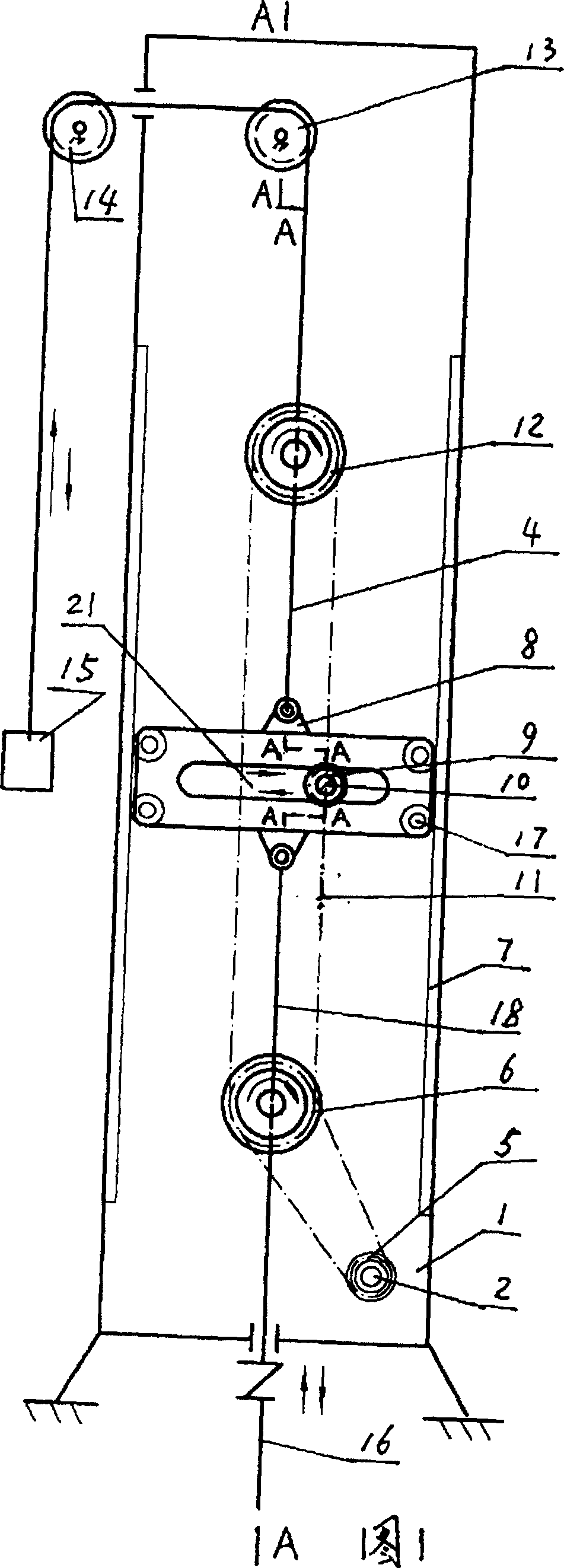
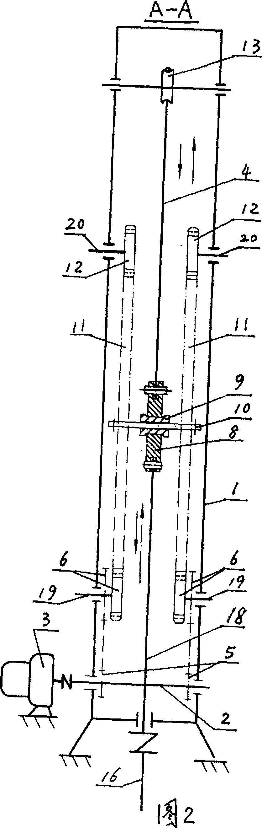
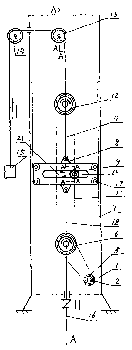
[0012] Hereinafter, the present invention will be further described by using the drawings and embodiments.

[0013] 1 and 2, the pumping unit has a frame 1, a reciprocating lifting mechanism and a driving device. The frame 1 has a quadrilateral frame structure. The reciprocating lifting pumping mechanism consists of guide slides 7 arranged on the two side walls of the frame 1, and the directional slide 8 is hinged to two guide wheels 17 respectively. The guide wheels 17 of the directional slide 8 are matched with the guide slide 7, and The frame 1 is provided with pulleys 13 and 14, the upper end of the directional slide 8 is connected with a steel cable 4, the upper steel cable 4 contacts the pulleys 13, 14 and is connected with the counterweight 15, and the lower end of the directional slide 8 is connected with a steel cable 18, The steel cable 18 at the lower end is connected to the sucker rod 16. The driving device consists of a drive shaft 2 connected to the electric reducer ...


PUM


Abstract

An oil pumping unit is characterized in that it includes a frame, and guide slides are arranged on both sides of the frame, and the directional slide with guide wheels cooperates with the guide slides, and the frame is provided with two There are two pulleys, the upper and lower ends of the directional slide plate are respectively connected with steel cables, the upper end of the steel cable contacts the two pulleys and is connected with the counterweight, and the lower end of the steel cable is connected with the sucker rod to form a reciprocating lifting and pumping mechanism; on the frame There is a driving shaft connected with the electric reducer, sprockets are respectively fixed at both ends of the driving shaft, and the two sprockets are respectively connected to the double sprocket through the chain, and the two double sprockets are respectively connected to the double sprocket through the chain. In addition, the sprockets are connected, and the two chains are fixed with a bridge shaft, and the pulley matched with the notch of the directional slide plate is mounted on the bridge shaft to form a driving device. It has the advantages of long sucker rod stroke, high oil pumping rate, compact structure, small size, light weight, energy saving, low manufacturing and operating costs, etc. This machine can also be used for pumping water, or as a power source for other machinery.

Description

Technical field [0001] The invention relates to an oil pumping unit related to an oil extraction operation machine. Background technique [0002] The existing pumping unit for oil production is mainly composed of a crank, a connecting rod, a walking beam, a donkey head, and a steel cable driven by a motor and a reducer. Its shortcomings are that the whole machine is large and heavy, consumes a lot of steel, the reciprocating stroke of the sucker rod is small, the pumping efficiency is low, and the manufacturing and operating costs are high. Summary of the invention [0003] The technical problem to be solved by the present invention is to provide an oil pumping system that can enlarge the stroke, long sucker rod stroke, high pumping efficiency, compact structure, small volume, light weight, saving steel, energy saving, and low manufacturing and operating costs. machine. This pumping unit can also be used for pumping water; or as a ...

Claims


Application Information

Patent Timeline
Patent Type & Authority Patents(China)
IPC IPC(8): F04B47/02
Inventor 郑常海
Owner 郑常海
Why Eureka
Try Eureka