Laser mark printing device for section steel

A laser marking and section steel technology, applied in the field of laser marking, can solve the problems of section steel marking and positioning and difficult to achieve assembly line operation, and achieve the effect of realizing assembly line operation.

Inactive Publication Date: 2009-07-08
武汉楚天激光(集团)股份有限公司
View PDF6 Cites 0 Cited by
  • Summary
  • Abstract
  • Description
  • Claims
  • Application Information

AI Technical Summary

Problems solved by technology

In addition, although there are also laser marking machines for metal materials on the market, such as: laser marking machines for bearings, laser marking machines for vernier calipers, etc., but, first, they are not used for large workpieces like steel Up to now, the laser device for marking on the steel has been marking the section steel by the method of color marking. The second is that it is difficult to realize the marking positioning and assembly line operation of large workpieces such as section steel.

Method used


Image

  • Laser mark printing device for section steel
  • Laser mark printing device for section steel
  • Laser mark printing device for section steel

Examples


Embodiment Construction

[0024] The following examples are used to illustrate the present invention, but are not intended to limit the scope of the present invention.

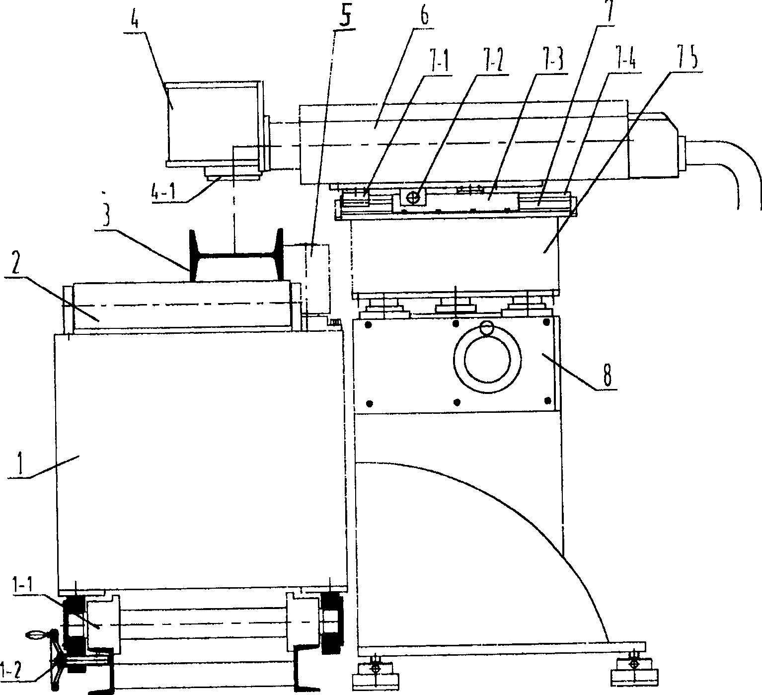
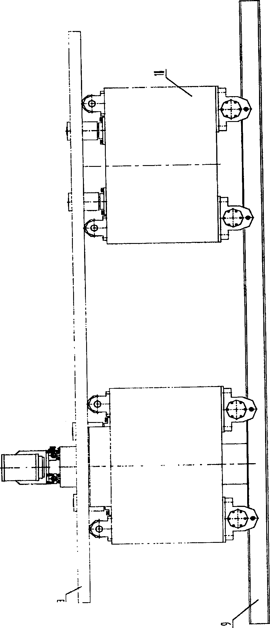
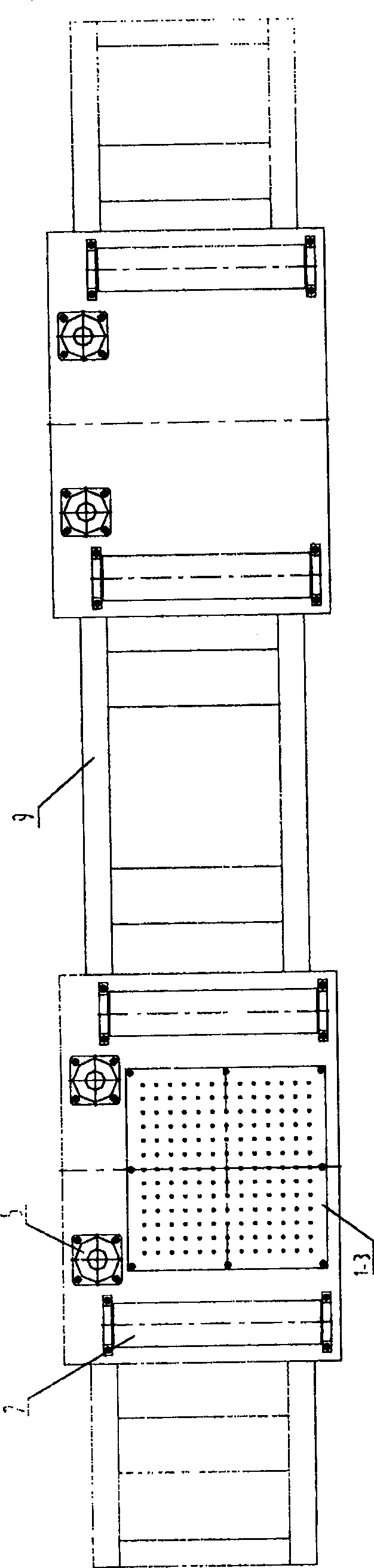
[0025] see figure 1 , figure 2 , the main components of the present invention are main workbench trolley 1, trolley wheels 1-1, trolley brake hand wheel 1-2, horizontal roller 2 for placing workpieces, workpieces waiting to be marked 3, two-dimensional scanning head 4, optical flat-field mirror 4-1. Vertical roller 5 for workpiece limit, laser 6, laser X-direction precision sliding table 7, laser Y-direction precision lifting mechanism 8, working trolley guide rail 9, driven working trolley 10.

[0026] see figure 1 , figure 2 , place the workpiece 3 on the main workbench trolley 1 and the driven work trolley 10, figure 1 The workpiece 3 in is an I-beam shown, and of course it can be other shaped steel, such as angle steel and channel steel. The workpiece 3 can roll on the horizontal roller 2. There are 2 pairs of horizontal rol...


PUM


Abstract

The present invention relates to laser printing field and discloses a laser printing device for profiled bar; the present invention comprises a computer system, a laser and an optical flat field mirror equipped under the laser emitting part; the present invention is characterized in that the present invention also comprises a main workbench small car, a work piece, a laser X directional precision slipway, a laser Y directional precision elevation mechanism, a guide way and a driven working small car; the main workbench small car and the driven working small car are equipped on the guide way and the work piece is placed on the upper surface of the main workbench small car and the driven working small car which is under the optical flat field mirror. The present invention boasts of high efficiency and does not affect the work piece function; the present invention can realize laser imprinting on large work piece which changes the operational mode that paint mark on the profiled bar manually and imprint permanent pattern and character on the profiled bar.

Description

technical field [0001] The invention relates to the field of laser marking, in particular to a laser marking device for section steel used in rolling mills and machinery factories. Background technique [0002] The existing marking method for profiled steel has been using the method of painting to mark the physical and chemical properties of the profiled steel. This method requires manual brushing (or spraying), that is, different color blocks are used to represent the profiled steel Different physical and chemical properties, and it is also necessary to formulate and implement the brushed graphics (including the combined shape of the color block shape) as a general identification standard, and its clarity, accuracy, and anti-counterfeiting are all affected to a certain extent , and the labor intensity is high and the efficiency is low, so that the corresponding brush marks are rarely seen on most section steels. In the world, in the process of circulating various types of s...

Claims


Application Information

Patent Timeline
Patent Type & Authority Patents(China)
IPC IPC(8): B41M5/24B23K26/00B23K26/362
Inventor 韩小平胡逸之易光纯周钢吴让大孙文
Owner 武汉楚天激光(集团)股份有限公司
Why Eureka
Try Eureka