Voltage regulator

A voltage regulator and voltage regulation technology, applied in the direction of adjusting electrical variables, control/regulating systems, instruments, etc., can solve the problems that the output voltage cannot provide the driving current in real time, the output voltage dips, etc., and achieve the rapid recovery of voltage dips. Effect

Inactive Publication Date: 2009-07-15
NOVATEK MICROELECTRONICS CORP
View PDF10 Cites 0 Cited by
  • Summary
  • Abstract
  • Description
  • Claims
  • Application Information

AI Technical Summary

Problems solved by technology

However, when the load current changes instantaneously, the output voltage will drop suddenly because it cannot provide enough driving current in real time.

Method used


Image

  • Voltage regulator
  • Voltage regulator
  • Voltage regulator

Examples


Embodiment Construction

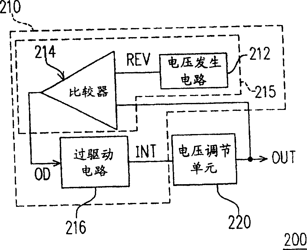
[0043] figure 2 It is a circuit block diagram of a voltage regulator according to an embodiment of the present invention. The voltage regulator 200 includes an overdrive unit 210 and a voltage adjustment unit 220. The voltage regulating unit 220 generates an output voltage OUT according to the input voltage INT. The output voltage OUT and the input voltage INT have a predetermined proportional relationship, and the proportional relationship can be determined by the circuit structure of the voltage regulating unit 220.

[0044] The overdrive unit 210 is coupled between the input terminal and the output terminal of the voltage adjustment unit 220, and adjusts the input voltage INT according to the comparison result of the output voltage OUT and the reference voltage REV. The overdrive unit 210 includes a voltage comparison circuit 215 and an overdrive circuit 216. The voltage comparison circuit 215 is coupled to the output terminal of the voltage regulator 200 to compare the outpu...


PUM


Abstract

A voltage regulator, which includes a voltage regulation unit and an overdrive unit. The voltage regulating unit outputs a corresponding output voltage according to the input voltage. The overdrive unit includes a voltage comparison circuit, coupled to the output terminal of the voltage regulator, for comparing the output voltage of the voltage regulator with a reference voltage, and outputting an overdrive signal; and an overdrive circuit, coupled to the voltage comparison circuit and the voltage between the input terminals of the adjustment unit, and adjust the input voltage of the voltage adjustment unit according to the overdrive signal, wherein if the output voltage is greater than the reference voltage, the overdrive signal is a low logic level, and the input voltage is a normal level; if the output If the voltage is lower than the reference voltage, the overdrive signal is at a high logic level, and the overdrive unit increases the level of the input voltage.

Description

Technical field [0001] The present invention relates to a voltage regulator, and more particularly to a voltage regulator that can adjust the input voltage in real time to maintain the output voltage level. Background technique [0002] The traditional voltage regulator usually has a stable voltage output when the load is not considered. However, when the load current changes instantaneously, the output voltage will not provide enough drive current in real time, which will cause the output voltage to drop sharply. Especially when it is necessary to provide a relatively large current driving capability, such as an LCD panel source driver, the phenomenon of voltage sag is more obvious. [0003] figure 1 It is a voltage regulator based on traditional technology. The voltage regulator 100 includes a voltage generator 110 and a voltage adjustment unit 120. Voltage generator 110 uses current source I REF The common node with the resistor R13 provides the input voltage INT to the nega...

Claims


Application Information

Patent Timeline
Patent Type & Authority Patents(China)
IPC IPC(8): G05F1/10
Inventor 颜志仁
Owner NOVATEK MICROELECTRONICS CORP
Why Eureka
Try Eureka