Ejection shaping mould set

A technology of injection molding and mold sets, which is applied in the field of injection molding mold sets, which can solve problems such as uneven cooling area, rise in mold surface temperature, and excessively long flow paths, and achieve the effects of improving cooling efficiency, shortening cooling time, and maintaining temperature balance

Inactive Publication Date: 2009-08-19
AU OPTRONICS CORP
View PDF6 Cites 0 Cited by
  • Summary
  • Abstract
  • Description
  • Claims
  • Application Information

AI Technical Summary

Problems solved by technology

However, most of the cooling circulating fluid in these parallel channels 11 can only cool the local position of the male mold cavity 51, which not only easily causes uneven cooling area, but also fails to achieve a good heat exchange effect, and its disadvantages are It takes a long cooling time after injection molding, and the formed product is prone to warping and deformation
[0004] Please also refer to Figure 4A , Figure 4B , the aforementioned female mold cavity 52 is located on the parting surface 201 of the female mold 20, and usually only an S-shaped runner 21 is provided inside the traditional female mold 20, and its position corresponds to the aforementioned female mold cavity 52; however, the S-shaped The runner 21 not only has the shortcoming that the flow path is too long, but also cannot form an effective thermal barrier between the hot runners on the left and right sides 521 of the female mold cavity 52
Since the temperature of the mold surface rises easily due to heat conduction and heat radiation between the different hot runners inside the master mold 20, thereby affecting the quality of the forming, how to design a better cooling water circuit to effectively cool down and prevent the internal temperature of the mold Imbalance becomes an important issue

Method used


Image

  • Ejection shaping mould set
  • Ejection shaping mould set
  • Ejection shaping mould set

Examples


Embodiment Construction

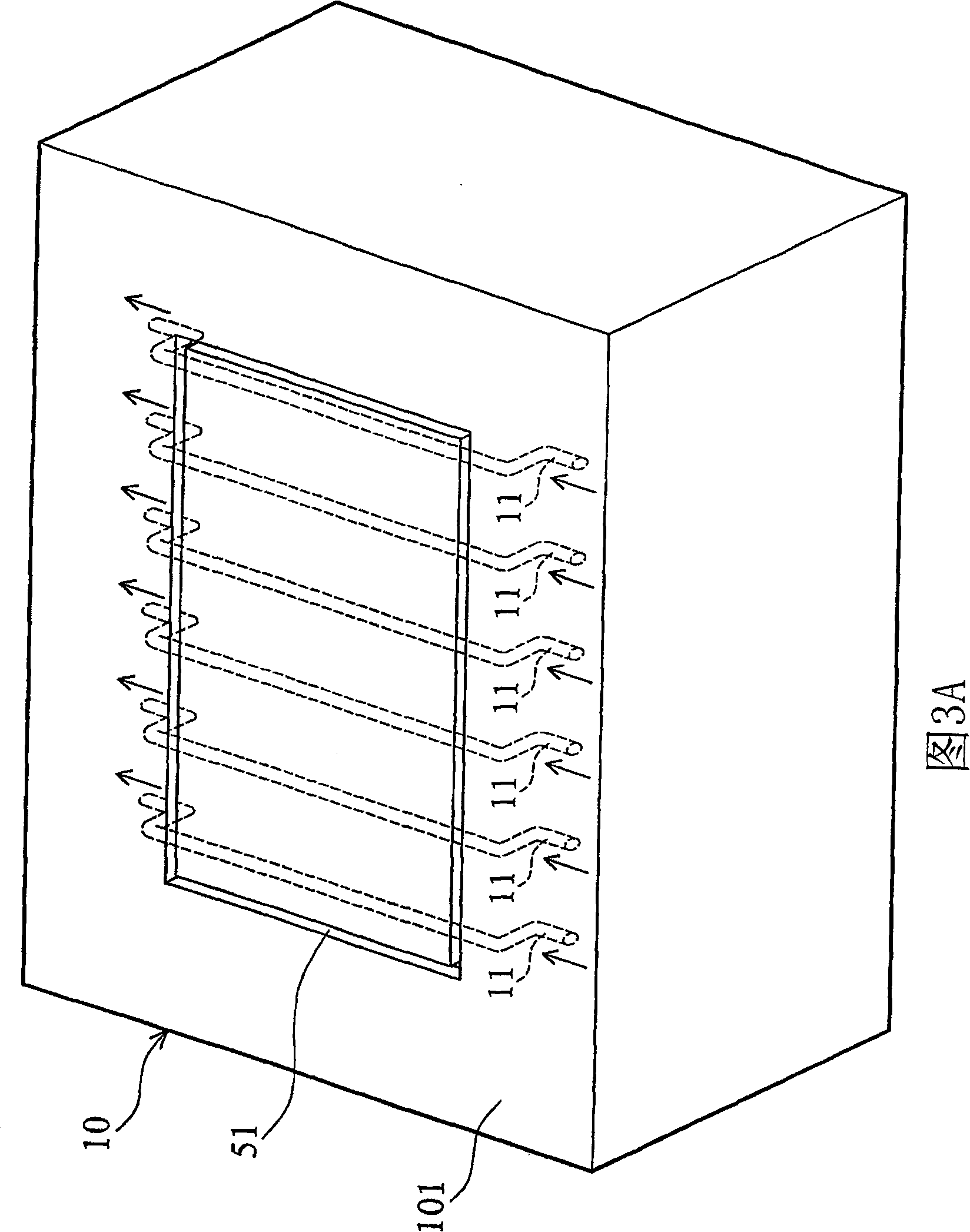
[0032] see Figure 5 , which shows a schematic diagram of the internal cooling water passage of the male mold 10 and the male mold cavity 51 in an injection molding mold set. The internal cooling water path of the male mold 10 in this embodiment mainly includes a plurality of parallel flow channels 12 and two curved flow channels 13, wherein the parallel flow channels 12 extend in the same direction and cross the opposite sides of the male mold cavity 51 The edge 512 ; the curved channel 13 is independent from the parallel channel 12 , wherein each curved channel 13 has a first section 131 and a second section 132 . Such as Figure 5 As shown, the first and second sections 131 , 132 are connected to each other to form an L-shaped structure, and their positions are respectively close to and parallel to the adjacent sides 511 , 512 of the male mold cavity 51 .

[0033] In this embodiment, by setting two bending runners 13 inside the male mold 10, the four sides of the male mol...


PUM


Abstract

The present invention discloses one kind of jetting formation mold assembly including one male mold and one female mold for producing rectangular plastic part. The male mold has one rectangular male mold cavity and one bent flow channel including one first section and one second section separately near to and parallel to two adjacent lateral sides. The female mold to be fitted with the male cavity has one female mold cavity and several heat running channels for plastic to be poured through and injected into the male mold cavity and the female mold cavity in producing the rectangular plastic part.

Description

technical field [0001] The invention relates to an injection molding die set, in particular to a cooling water circuit design of the injection molding die set. Background technique [0002] See first figure 1 Generally, the backlight module of a flat-panel display mostly includes a rectangular plastic frame P for fixing a light guide plate or other optical elements, wherein the plastic frame can be manufactured by injection molding. see next figure 2 , the injection molding mold set used to manufacture the plastic frame P mainly includes a male mold 10, a female mold 20, and an injection nozzle 30, wherein the plastic can pass through the multiple hot runners 40 inside the female mold 20 from the injection nozzle 30. Injected into the forming area 50, so as to make the aforementioned plastic frame P; as figure 2 As shown, the aforementioned forming area 50 is composed of a male mold cavity 51 on the male mold 10 and a female mold cavity 52 on the female mold 20 . [00...

Claims


Application Information

Patent Timeline
Patent Type & Authority Patents(China)
IPC IPC(8): B29C45/26B29C45/73
Inventor 陈唐博郑文源黄俊玮
Owner AU OPTRONICS CORP
Why Eureka
Try Eureka