Cord string branch dome

A chord-supported dome and cable-rod technology, used in roofs, building components, buildings, etc., can solve the problems of increasing the burden of supporting structures, increasing the stress of compression rods and edge ring beams, and being unable to self-adjust, so as to improve stability and performance. Effect of ultimate bearing capacity, roof stiffness improvement and restraint enhancement

Inactive Publication Date: 2009-08-26
BEIJING UNIV OF TECH
View PDF4 Cites 2 Cited by
  • Summary
  • Abstract
  • Description
  • Claims
  • Application Information

AI Technical Summary

Problems solved by technology

[0003] (1) The upper and lower floors of the cable dome structure are both flexible systems, and the rods other than the struts cannot bear the pressure, which makes the construction of the cable dome very difficult. Although it has been around for many years, there are few actual structures built so far
[0004] (2) In order to ensure that all the cables of the cable dome structure are in tension, the prestress level must be increased to increase the stress of the compression rod and edge ring beam, so it is necessary to set a very firm support or place a Huge ring beams are arranged, which increases the burden on the supporting structure and wastes materials
[0007] (5) The internal force of the single-layer reticulated shell on the upper layer of the suspensive dome is passively generated by the lower layer of steel cables and external loads, and cannot self-adjust the internal force, so that most of the hoop members of the upper single-layer reticulated shell are passively compressed and cannot be self-adjusted to reduce the stress. little pressure

Method used


Image

  • Cord string branch dome
  • Cord string branch dome
  • Cord string branch dome

Examples


Embodiment 1

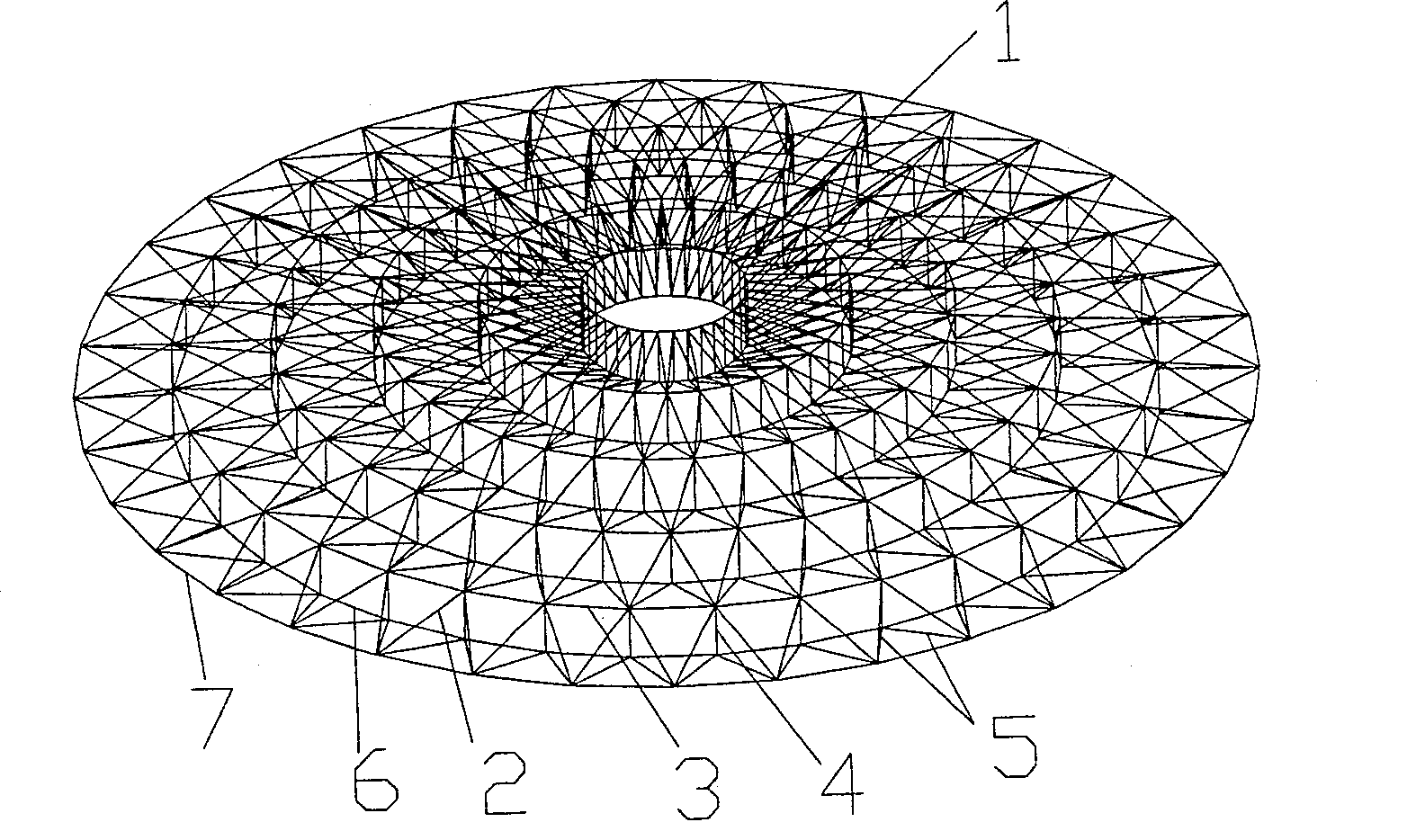
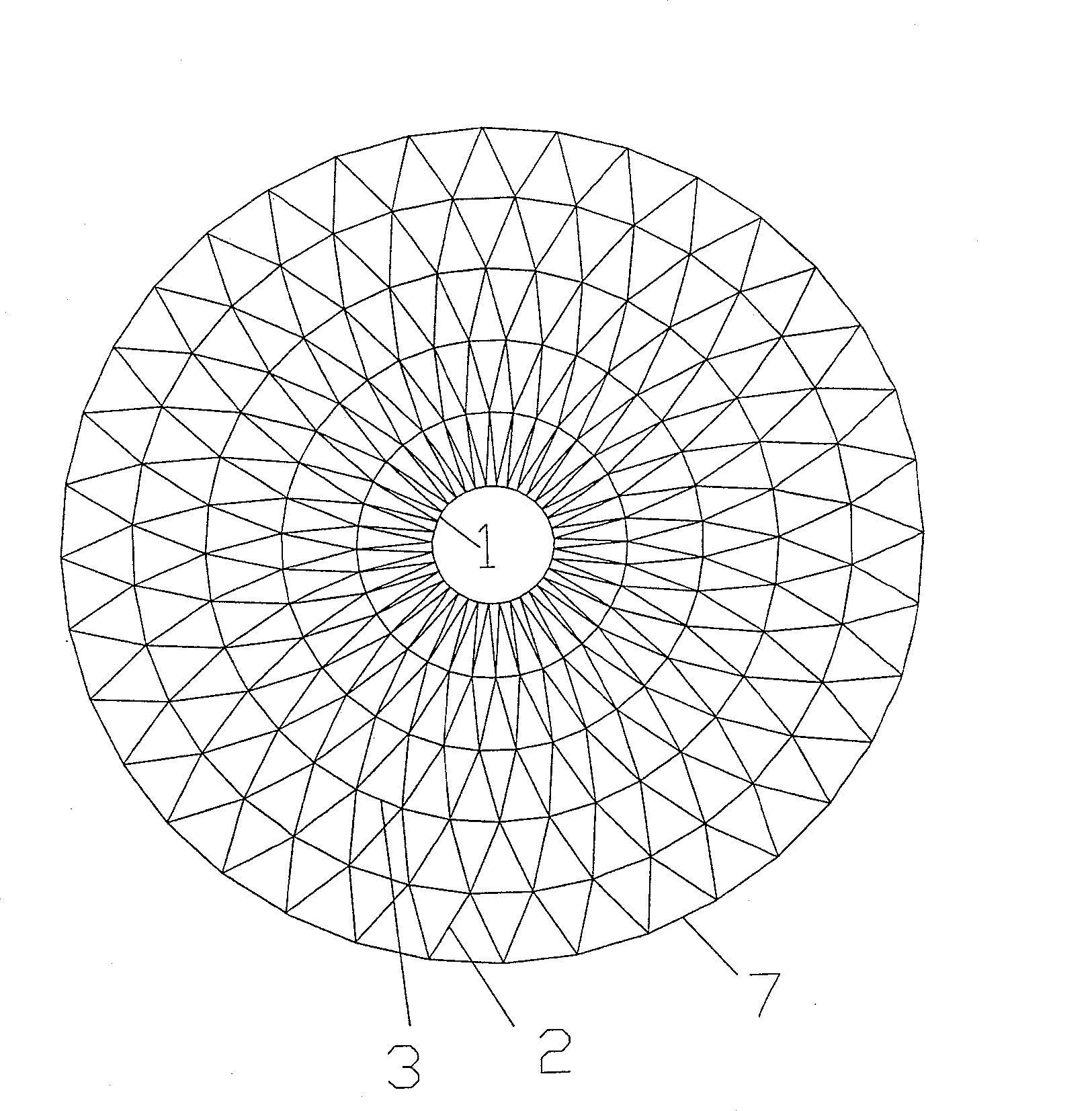
[0035] Such as figure 1 , figure 2 , Figure 4 , Image 6 As shown, this embodiment mainly includes upper and lower parts. The upper layer is composed of a central pressure ring 1, an upper radial rod 2, an upper ring cable 3 and a side ring beam 7. The upper radial rod 2 is connected with the central ring beam at the center of the dome. 1 is hinged, hinged with the side ring beam 7 at the periphery, and hinged with the upper ring cable 3 in the middle, arranged in a joint square grid, and the outline shape of the grid is circular. The lower layer is composed of the lower radial cable 5, the lower ring cable 6 and the strut 4. The upper end of the strut 4 is connected to the node of the upper layer, and the lower end is connected to the node of the lower layer; Its cross end is connected with the lower end of the strut 4, and the other two ends are respectively connected with different nodes of the upper layer. The lower hoop cable 6 is closed and arranged along the hoop ...

Embodiment 2

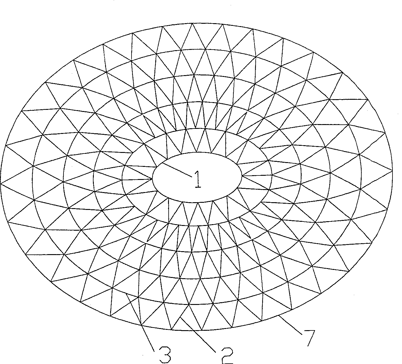
[0038] Such as image 3 , Figure 5 As shown, the structure of this embodiment is the same as that of Embodiment 1, the only difference is that the shape of the grid formed by the upper central pressure ring 1, the upper radial rod 2, the upper ring cable 3 and the side ring beam 7 is Oval. The length of strut 4 should guarantee that the angle of intersection between lower radial cable 5 and strut 4 is 70 degrees. The upper ring cable 3, the lower radial cable 5, and the lower ring cable 6 are selected as steel hinge lines, and the upper radial rod 2 is selected as a square steel pipe.

Embodiment 3

[0040] The structure of this embodiment is the same as that of Embodiment 1, the only difference is that the outline shape of the mesh composed of the upper central pressure ring 1, upper radial rod 2, upper ring cable 3 and side ring beam 7 is polygonal. The length of strut 4 should guarantee that the angle of intersection between lower radial cable 5 and strut 4 is 55 degrees. The upper ring cable 3, the lower radial cable 5, and the lower ring cable 6 are selected as cables, and the upper radial rod 2 is selected as section steel.


PUM


Abstract

The invention relates to a dome used in the construction field, in particular to a cable-strut suspensive dome. It consists of upper and lower parts. The upper layer includes a central pressure ring (1), an upper radial rod (2), an upper ring cable (3) and an edge ring beam (7). The upper radial rod (2) is connected to the center of the dome The central pressure ring (1) is connected, the periphery is connected with the side ring beam (7), the middle is connected with the upper ring cable (3), and the upper layer is arranged in a grid shape. The lower layer includes a lower radial cable (5), a lower ring cable (6) and a strut (4). The lower end of the rod (4) is connected to the upper node, and the lower hoop cable (6) is also connected to the junction of the lower radial cable (5) and the strut (4). The lower hoop cable is closed and arranged along the hoop direction. The layers meet at the edge ring beam. The structure of the present invention is simple in force, the stability of the bar member of the pressure bar and the overall stability of the whole structure are high, and the ultimate bearing capacity is large.

Description

technical field [0001] The invention relates to a dome used in the construction field, in particular to a cable-strut suspensive dome. Background technique [0002] In recent years, with the development of prestressed steel structures, a large number of new structural systems have emerged, such as cable domes and suspension dome structures. The cable dome has the characteristics of simple structure, light system, and most of the components are tension members; the suspension dome is a new structure formed by combining the cable dome and the single-layer reticulated shell, which increases the roof rigidity and reduces the construction cost. difficulty. However, these two structural systems also have the following shortcomings: [0003] (1) The upper and lower layers of the cable dome structure are flexible systems, and the rods except the struts cannot bear the pressure, which makes the construction of the cable dome very difficult. Although it has been around for many year...

Claims


Application Information

Patent Timeline
Patent Type & Authority Patents(China)
IPC IPC(8): E04B7/08E04B7/14E04B1/342
Inventor 张爱林刘学春张庆亮王冬梅李鹏飞鞠晓臣王敬仁
Owner BEIJING UNIV OF TECH
Why Eureka
Try Eureka