Reciprocating multi-row grate type domestic refuse incinerator

A domestic waste incineration, multi-column technology, applied in the field of domestic waste incineration equipment, can solve the problems of poor operability, large size, and inability to adjust the drive mechanism of the grate separately

Active Publication Date: 2009-09-02
WAI MING ENVIRONMENTAL PROTECTION EQUIP
View PDF6 Cites 4 Cited by
  • Summary
  • Abstract
  • Description
  • Claims
  • Application Information

AI Technical Summary

Problems solved by technology

[0002] The applicant applied for a patent on a domestic waste incinerator on April 23, 2002. The authorized announcement number of this patent is CN1162646C. The reciprocating multi-row grate domestic waste incinerator provided by this invention includes a furnace with a hopper The body, the feeder installed in the furnace body, the fire grate, the air chamber under the fire grate, and the slag extractor, wherein the fire grate sheet contains fixed pieces fixed on the furnace body and arranged at intervals between two adjacent fixed pieces The grate is divided into a front section and a rear section along the garbage running direction. The front section close to the hopper is a downward-sloping reverse-push grate, and the rear section is a forward-push grate. There is a drop of height H at the junction of the grate, but this kind of incinerator has the following defects: 1. The grate of the combustion furnace has only two rows at most, and the grate has a size limit, so it is not conducive to the increase of the burning area of ​​the grate ; 2. The damper used to adjust the air volume of the furnace is unreliable, and its transmission adopts a multi-point connecting rod device, which is prone to stuck and out of place during operation. 3. In the original incinerator, two rows of furnaces The grate is driven by the same drive mechanism, so it is impossible to adjust the drive mechanism of the grate individually according to the different conditions of the garbage, and to control each row of grate independently, which is poor in operability

Method used


Image

  • Reciprocating multi-row grate type domestic refuse incinerator
  • Reciprocating multi-row grate type domestic refuse incinerator
  • Reciprocating multi-row grate type domestic refuse incinerator

Examples


Embodiment Construction

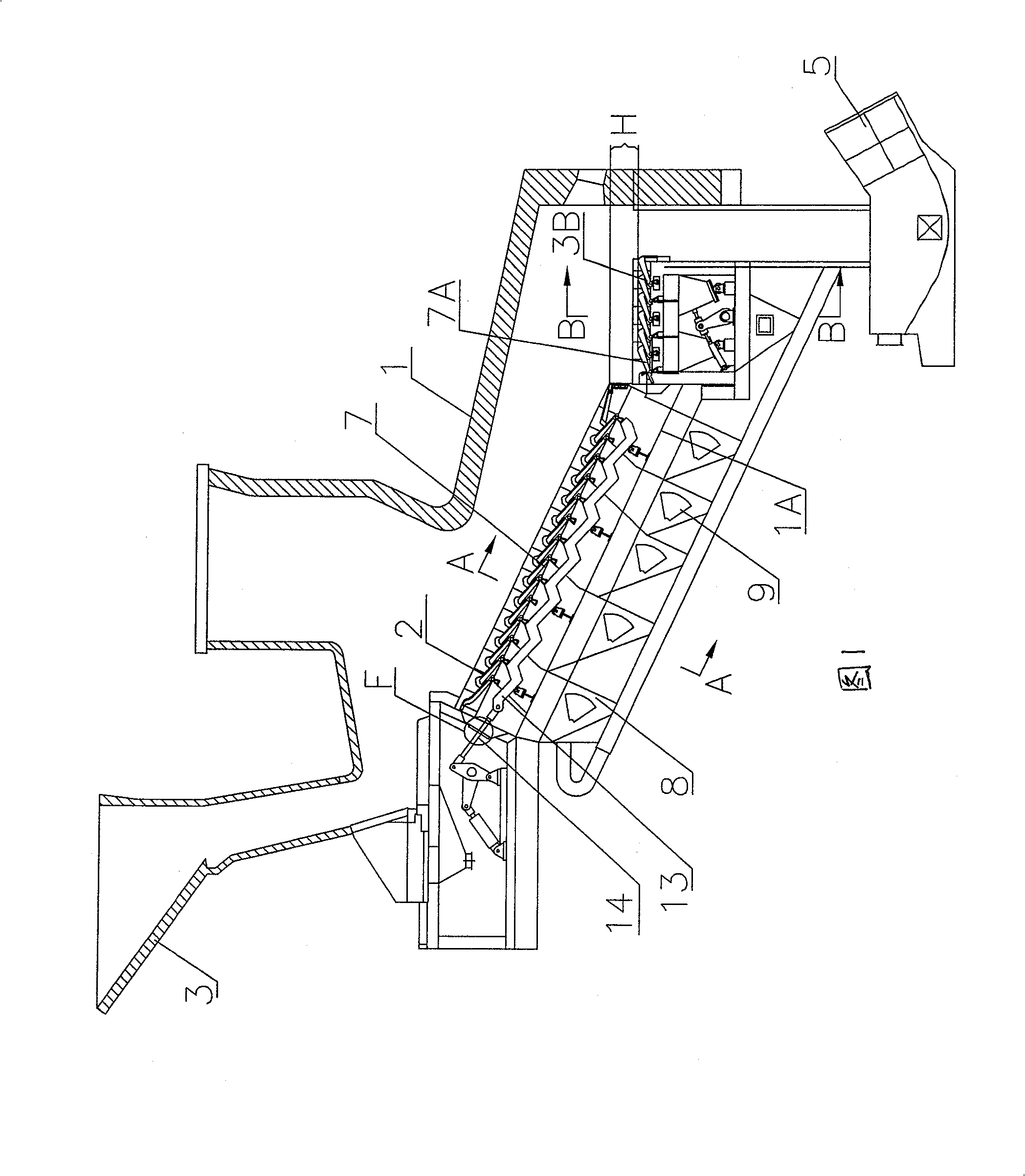
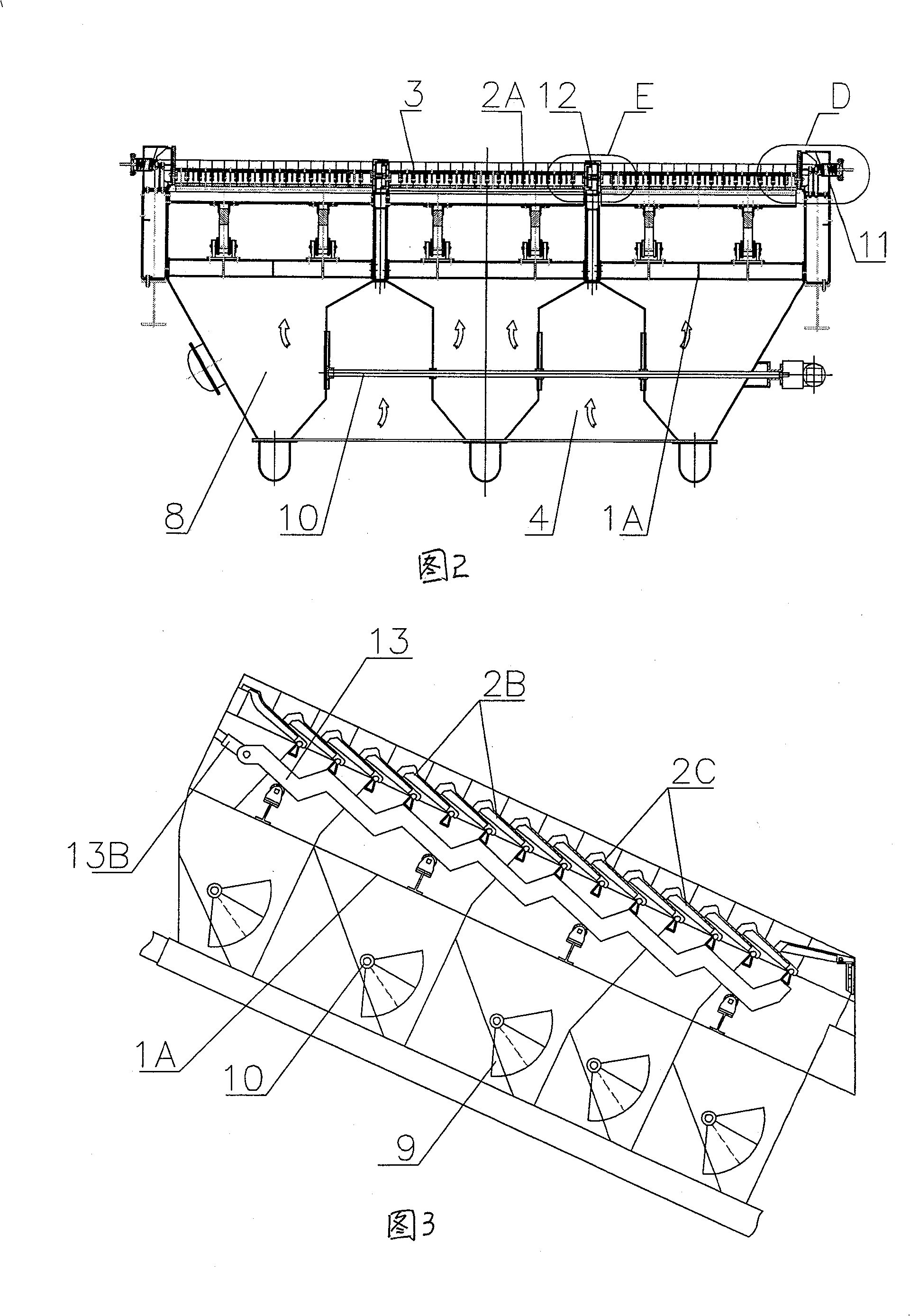
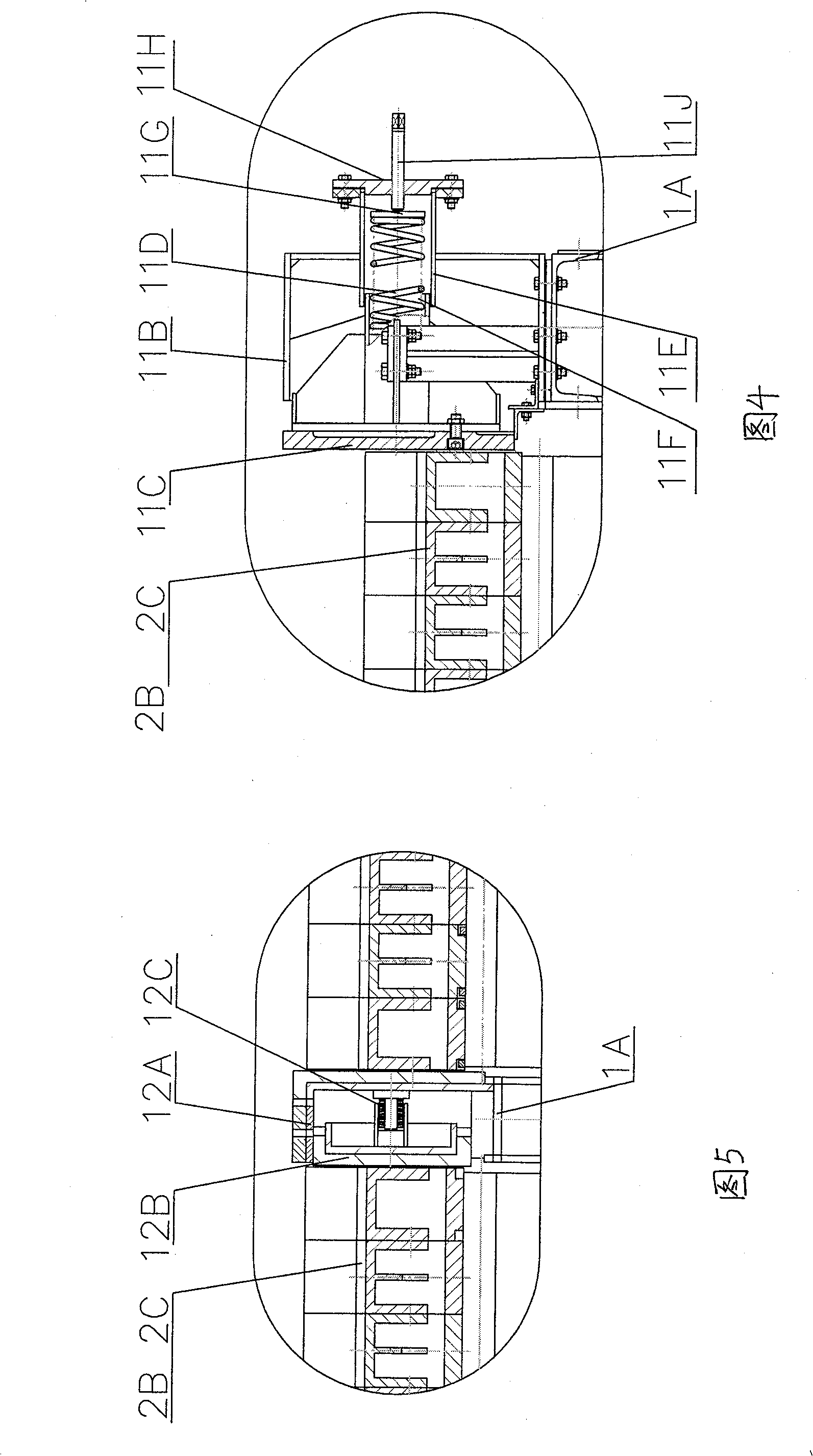
[0018] Such as figure 1 , figure 2 As shown, the reciprocating multi-row grate household waste incinerator of the present invention comprises a furnace body 1, a grate support 1A is arranged on the furnace body 1, a fire grate 2 is arranged on the grate support 1A, and the first and last ends of the furnace body 1 are respectively A hopper 3 and a slag extractor 5 are provided, and an air chamber 4 is arranged under the grate 2. The grate 2 includes a fixed grate piece 2B fixed on the grate bracket 1A and a movable grate piece 2C, and the movable grate piece 2C is arranged at intervals before and after Between two adjacent fixed grate pieces 2B and connected with the movable bracket 13, there are at least three rows of grate 2 arranged on the grate bracket 1A, and each row of grate 2 includes a fixed grate piece 2B, a movable grate piece 2C and a movable grate piece 2C The drive mechanism of the middle fire grate 2 in the fire grate 2 is equipped with an intermediate sealing...


PUM


Abstract

The invention discloses a reciprocating multi-row grate domestic waste incinerator, which comprises a furnace body, a grate bracket is arranged on the furnace body, a grate is arranged on the grate bracket, an air chamber is arranged under the grate, and It includes fixed grate pieces and movable grate pieces fixed on the grate bracket. The movable grate pieces are arranged at intervals between two adjacent fixed grate pieces. There are at least three rows of grate on the grate bracket. The drive mechanism of the grate, the movable grate and the movable grate; the side end of the middle grate in the grate is equipped with an intermediate sealing compensation device; the bottom of the grate is provided with multiple groups of compartments according to the combustion section along the moving direction of the garbage. The number of compartments included in a group of compartments is the same as the number of rows of fire grates, and each compartment of the same group corresponds to each row of fire grates. With adjustable air intake damper. The incinerator can greatly increase the garbage incineration area on the basis of realizing the function of the original incinerator, and can realize separate control of each column of fire grates to improve operability.

Description

technical field [0001] The invention relates to an incineration device for domestic garbage, which is mainly used for incinerating unsorted domestic garbage with low calorific value and high moisture content. Background technique [0002] The applicant applied for a patent on a domestic waste incinerator on April 23, 2002. The authorized announcement number of this patent is CN1162646C. The reciprocating multi-row grate domestic waste incinerator provided by this invention includes a furnace with a hopper The body, the feeder installed in the furnace body, the fire grate, the air chamber under the fire grate, and the slag extractor, wherein the fire grate sheet contains fixed pieces fixed on the furnace body and arranged at intervals between two adjacent fixed pieces The grate is divided into a front section and a rear section along the garbage running direction. The front section close to the hopper is a downward-sloping reverse-push grate, and the rear section is a forward...

Claims


Application Information

Patent Timeline
Patent Type & Authority Patents(China)
IPC IPC(8): F23G5/00
Inventor 项光明
Owner WAI MING ENVIRONMENTAL PROTECTION EQUIP
Why Eureka
Try Eureka