Vehicle occupant protection device

A technology for occupant protection and vehicles, which is applied in the technical field of improvement of occupant protection devices for vehicles, and can solve problems such as increasing the number of installation parts, increasing the number of parts, and difficulty in unifying the positional relationship of the inflating mechanism.

Inactive Publication Date: 2009-09-23
HONDA MOTOR CO LTD
View PDF6 Cites 1 Cited by
  • Summary
  • Abstract
  • Description
  • Claims
  • Application Information

AI Technical Summary

Problems solved by technology

Since the inflation mechanism and the top side airbag are respectively installed on the top side guide rail, it is difficult to unify the positional relationship of the top side airbag relative to the inflation mechanism
As a result, there may be a situation where the top side airbag is fixed in a twisted state with respect to the inflator
This twisting phenomenon is unfavorable for the gas of the inflation mechanism to be smoothly supplied into the top side airbag, and for the top side airbag to be inflated and deployed smoothly and stably.
[0031] In addition, since the inflator and the top-side airbag are separately mounted on the top-side rail, the number of mounting locations increases, resulting in an increase in the number of parts, which in turn increases the number of assembly steps.
[0032] In addition, the gas generated by the inflatable mechanism becomes a pulsating airflow and flows into each cavity through the inner tube. inside the lumen, thereby preventing the lumen from expanding and deploying stably

Method used


Image

  • Vehicle occupant protection device
  • Vehicle occupant protection device
  • Vehicle occupant protection device

Examples


Embodiment Construction

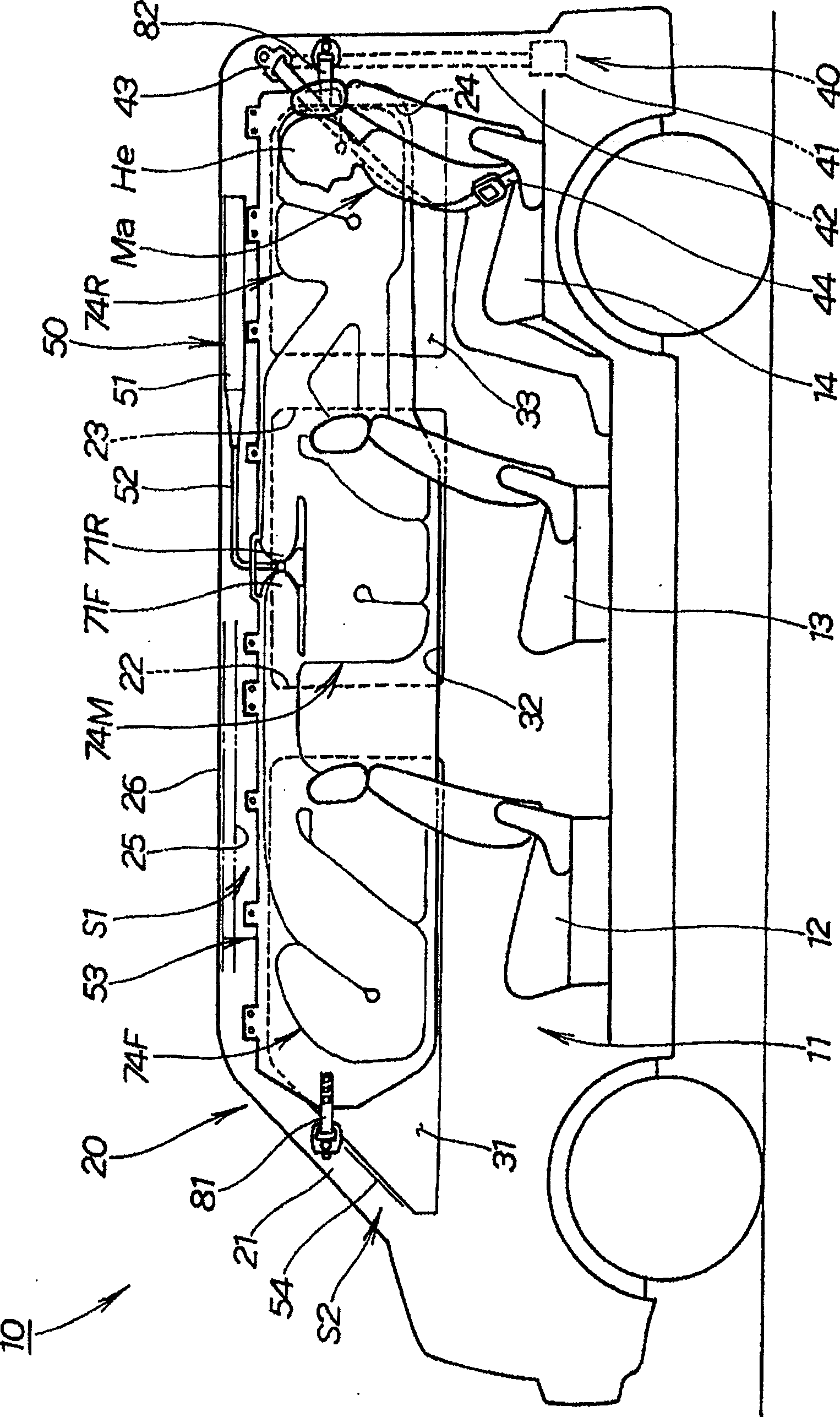
[0113] Preferred embodiments of the present invention will be described below in conjunction with the accompanying drawings. Here, front, rear, left, and right are based on the driver's viewpoint.

[0114] figure 1 It is a side view of the vehicle of the present invention viewed from the interior side, showing a state in which the vehicle occupant protection device 50 is mounted on the vehicle 10 (the roof side airbag 53 is deployed).

[0115] Here, as for the occupant protection device 50 for a vehicle, only the structure arrange|positioned at the right side of the vehicle 10 is shown. Since the vehicle occupant protection device 50 on the left side has the same structure as that on the right side, description thereof will be omitted.

[0116] The vehicle 10 is a motor vehicle generally called a minivan, in which three front and rear rows of seats including front seats 12 , middle seats 13 , and rear seats 14 are provided in a cabin 11 .

[0117] The structure of the vehic...


PUM


Abstract

PROBLEM TO BE SOLVED: To provide an occupant protecting device for a vehicle capable of putting its air bag alongside a vehicle in good performance and conducting the air bag mounting operation with less time. SOLUTION: The occupant protecting device 50 for the vehicle is structured so that a roof side air bag 53 in the folded-up condition is covered with a cover 91, the head 132 of a clip 131 is arranged inside the cover 91, and that an engagement part 133 is protruded to the outside of the cover 91 and is engaged with the vehicle 10. On the base part 134a of the engagement part 133 of this device 50, a hold-down part 136 is provided on the outside of the cover 91, and is pressed from outside the cover 91 so that the engagement part 133 is engaged with the vehicle 10. COPYRIGHT: (C)2006,JPO&NCIPI

Description

technical field [0001] The present invention relates to an occupant protection device for a vehicle, in which an airbag is installed along the roof, and the airbag is inflated and deployed from a folded state by the action of an inflation mechanism. The present invention also relates to an improved technology of a vehicle occupant protection device, which can strengthen the protection of the roof side part of the vehicle for the occupant when the side part is subjected to impact force. Background technique [0002] In recent years, development of a technique for improving protection especially for the head of an occupant when a side portion of a vehicle is hit is underway. [0003] In such a vehicle occupant protection device, for example, a technology is being developed (for example, Japanese Patent No. 3510061, hereinafter referred to as Patent Document 1), wherein a roof side airbag is accommodated from a pillar along the side edge of the roof, and When receiving an impa...

Claims


Application Information

Patent Timeline
Patent Type & Authority Patents(China)
IPC IPC(8): B60R21/20B60R21/201B60R21/213
Inventor 青木孝志户塚广文斋藤雄一
Owner HONDA MOTOR CO LTD
Why Eureka
Try Eureka