Automatic stop charging control circuit of positive and negative combination pulse charge machine

A technology of controlling circuits and combining pulses, applied in battery circuit devices, electric vehicles, circuit devices, etc., can solve the problems of reducing battery capacity and service life, coarse grains of plates, overcharging, etc. The effect of saving electricity and avoiding water loss

Inactive Publication Date: 2009-10-07
陈荣森 +1
View PDF4 Cites 0 Cited by
  • Summary
  • Abstract
  • Description
  • Claims
  • Application Information

AI Technical Summary

Problems solved by technology

But at present, no matter what kind of charging mode, it is impossible to stop charging immediately when the battery is just fully charged (that is, 100% fully charged), so it often causes overcharging.
Especially charge the battery overnight at night. After the battery is fully charged, the charger will automatically switch to the low-current float charge stage. This floating charge overcharge phenomenon will easily cause the battery electrolyte to lose water and the irreversible plate grains to coarsen. , long-term overcharging will rapidly reduce the capacity and service life of the battery

Method used


Image

  • Automatic stop charging control circuit of positive and negative combination pulse charge machine
  • Automatic stop charging control circuit of positive and negative combination pulse charge machine

Examples


Embodiment Construction

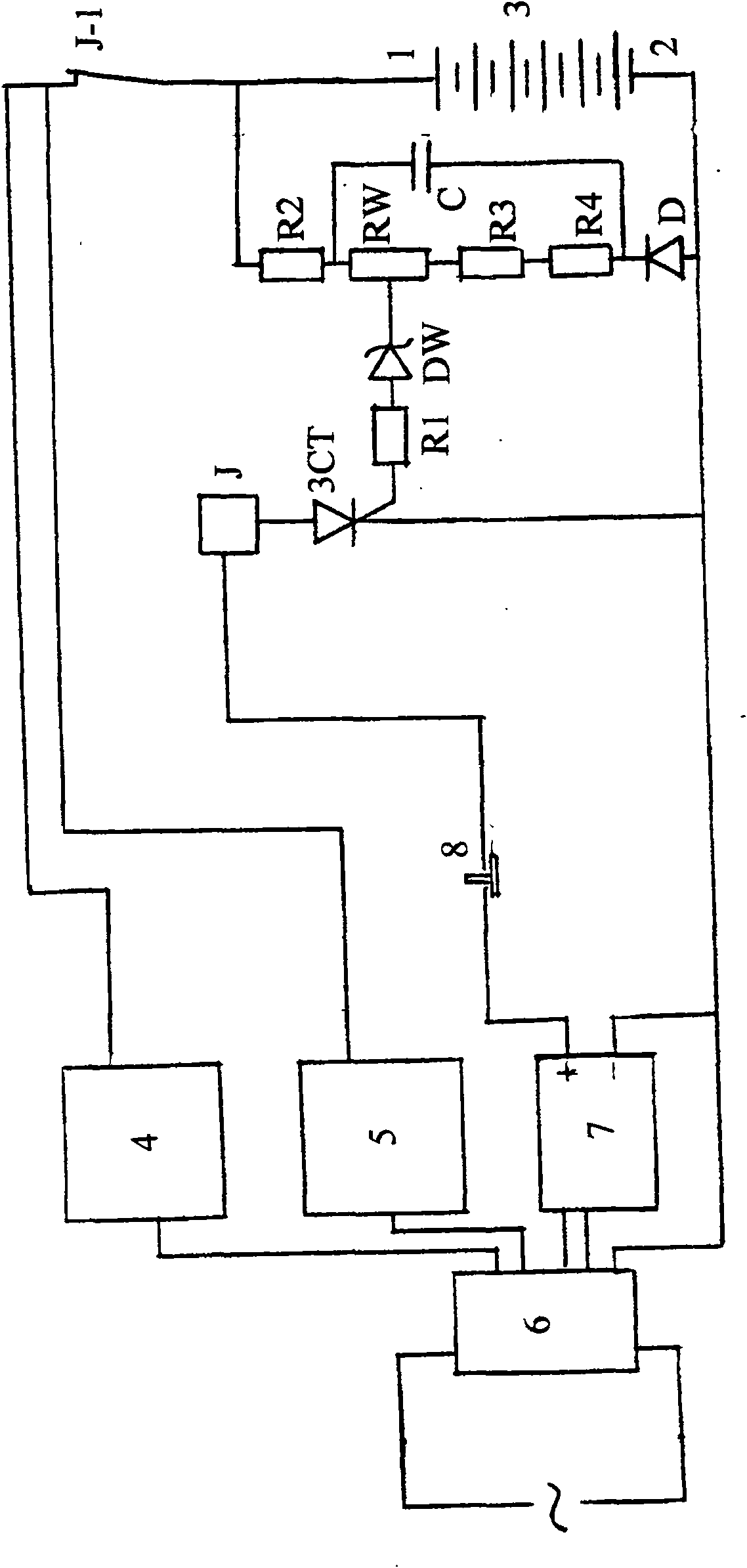
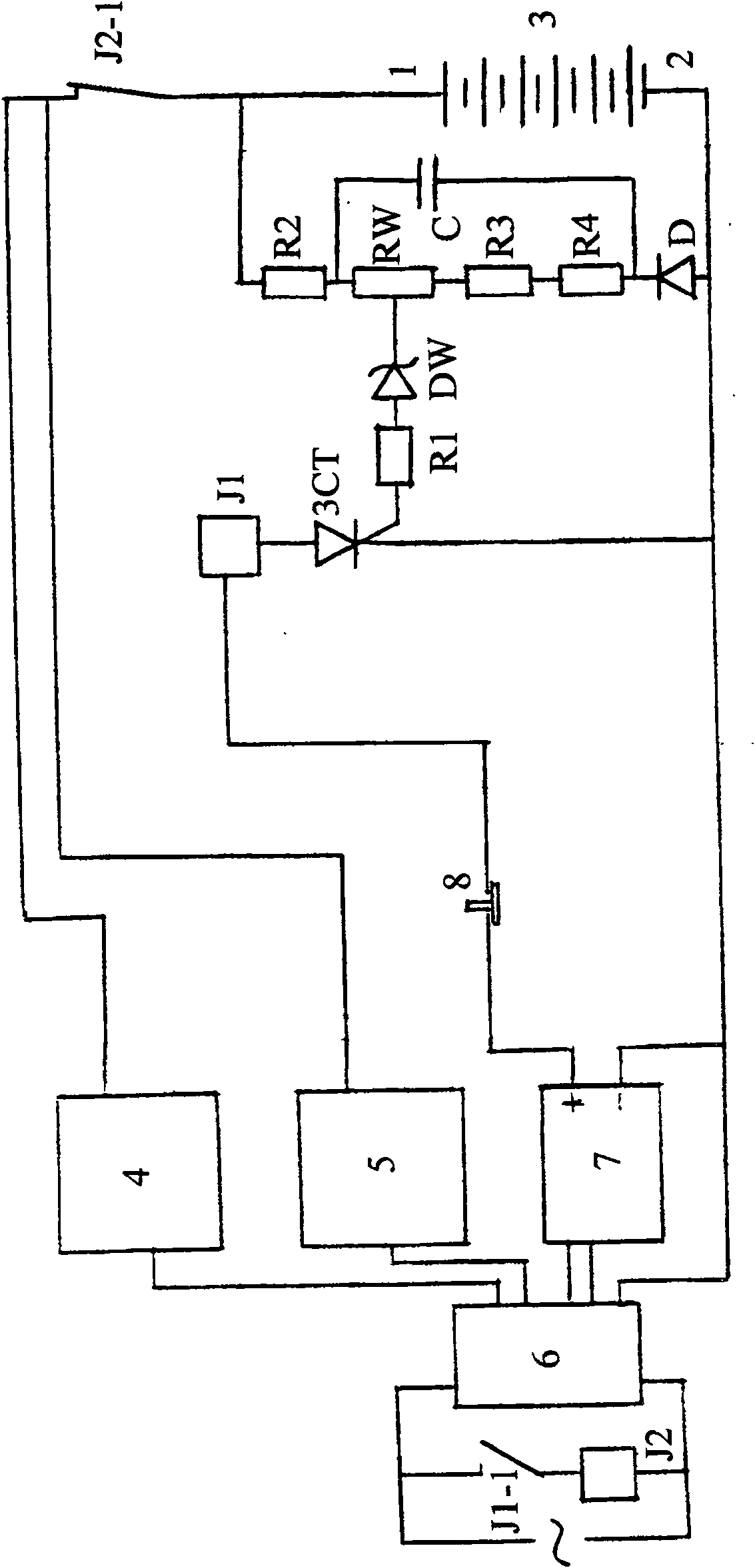
[0011] see figure 1 As shown, the automatic stop charging control circuit of the positive and negative combination pulse charger of the present invention is composed of first to fourth resistors R1 to R4, variable resistor RW, capacitor C, diode D, Zener diode DW, thyristor 3CT, Composed of relay J, wherein: the anode of the diode D is connected to the charging negative pole 2 of the charger; the second resistor R2, the variable resistor RW, the third resistor R3 and the fourth resistor R4 are sequentially connected in series between the charging positive pole 1 of the charger and the diode D Between the cathodes; one end of the relay J is connected to the positive pole of the regulated power supply 7 of the charger, and the other end is connected to the anode of the thyristor 3CT; the cathode of the thyristor 3CT is respectively connected to the negative pole of the regulated power supply 7 and the negative pole 2 of the charger, Its control pole is connected to the middle en...


PUM


Abstract

The invention belongs to the accumulator charging controlling field, wherein a diode D anode of an automatic charging stopping controlling circuit of a positive and negative combination impulse charging device is connected with a charging negative electrode, a second electric resistance R2, a variable resistance RW, a third electric resistance R3 and a fourth electric resistance R4 are connected in series in turn between a charging positive electrode and the diode D cathode, one end of a relay J or a first relay J1 is connected with a positive pole of a constant voltage power supply, the other end is connected with an anode of a silicon controlled rectifier 3CT, a cathode of the silicon controlled rectifier 3CT is respectively connected with a negative pole of the constant voltage power supply and the charging negative electrode, a controlling electrode is connected with the middle end of the variable resistance RW through the first electric resistance R1 and a constant voltage diode DW in turn, one end of a capacitance C is connected between the second resistance R2 and the variable resistance RW, the other end is connected between the fourth electric resistance R4 and the diode D cathode, a normally-closed contact J-1 or J-2 of the relay J or a second relay J2 is connected in series on the circuit that the charging anode is connected with one input end of the positive and negative impulse charging circuit, and a normally-closed contact J1-1 of the first relay J1 is connected with the second relay J2 on two input circuits of an alternating current power supply. The invention solves the technical problem that an accumulator is prevented from over charging.

Description

Technical field: [0001] The invention belongs to the field of storage battery charging control, in particular to an automatic stop charging control circuit used for positive and negative combined pulse chargers to prevent overcharging. Background technique: [0002] In the process of long-term practice and exploration, people have found that the capacity and service life of rechargeable batteries have a huge relationship with the user's charging mode in addition to the manufacturing quality of the battery itself. Therefore, various charging modes and the use of this charging mode Charging equipment has come out one after another. Among them, the charger that uses positive and negative combined pulses to charge the battery is widely used by all walks of life because it can make the battery's capacity after each charge is more than 90% of the nominal capacity, and the battery has a long service life. Attention. But no matter what kind of charging mode at present, it is imposs...

Claims


Application Information

Patent Timeline
Patent Type & Authority Patents(China)
IPC IPC(8): H02J7/00H02J7/10H02H7/18
Inventor 苏永贵
Owner 陈荣森
Why Eureka
Try Eureka