
Real time detector for shallow sea near bottom transport silt concentration and grain size

A real-time detection and near-bottom technology, applied in the direction of analyzing materials and instruments, can solve problems such as seabed scour or sedimentation, hazards of offshore engineering facilities, and sand traps that cannot monitor the amount of incoming sand and particle size composition in real time

Inactive Publication Date: 2009-10-14
OCEAN UNIV OF CHINA
View PDF7 Cites 0 Cited by
  • Summary
  • Abstract
  • Description
  • Claims
  • Application Information

AI Technical Summary

Problems solved by technology

[0002] The sediment near the bottom of the shallow sea migrates under the action of waves and currents, which often leads to erosion or deposition of the seabed, causing damage to offshore engineering facilities
Existing sand traps are widely used in the capture of shallow sea and near-bottom transported sediment. Generally, after a tidal cycle is taken up, it is brought back to the laboratory to analyze the amount of incoming sediment and particle size components (particle size distribution) in different directions during the entire tidal cycle. ), this kind of sand trap cannot monitor in real time the amount of incoming sand and particle size composition (particle size distribution) under different flow rates and different sea conditions; in addition, although there are laser suspension sonar and laser suspension particle size distribution sonar equipment in modern times, they can monitor water separately. The concentration and particle size distribution of suspended matter, but they must use the hull to detect the concentration and particle size of fine particle suspended matter in the water, and it is difficult to detect the concentration and particle size distribution of sediment moving in the form of shifting and jumping near the bottom

Method used


Image

  • Real time detector for shallow sea near bottom transport silt concentration and grain size
  • Real time detector for shallow sea near bottom transport silt concentration and grain size

Examples


Embodiment Construction

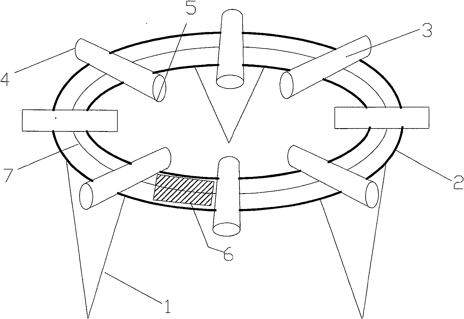
[0012] like figure 1 , the present invention includes eight cylinders 3 arranged radially at 45 angle intervals fixed on the circular cavity 2, on which a concentration probe 5 and a particle size probe 4 are arranged, and via cables 7 and corresponding data The acquisition device 6 is connected, and the above-mentioned cable 7 and the corresponding data acquisition device 6 are all encapsulated in the ring cavity 2 . In this way, the above-mentioned degree and particle size distribution of the sediment passing through the device in different directions can be detected on site in real time.

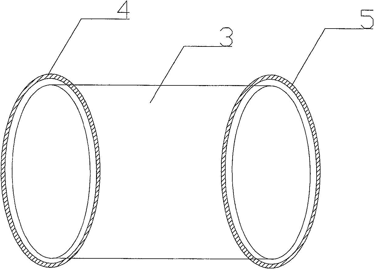
[0013] like figure 2 , in order to facilitate the process, the concentration probe and the particle size probe are installed in the same ring cavity, usually at both ends of the same ring cavity, and the positions of the two can be interchanged. The above-mentioned circular cavity 2 is a metal circular cavity or a circular body bent from a plastic tube, and the cable and the data acqui...


PUM


Abstract

The invention relates to a real-time detection device for the concentration and grain size of sediment transported near the bottom in shallow sea. It includes eight cylinders fixed on the circular cavity at intervals of 45 degrees around the circumference and arranged radially. The cylinders are equipped with concentration probes and eight particle size probes, and are connected to corresponding data acquisition and processing devices via cables. The above-mentioned Cables and corresponding data acquisition and processing devices are packaged in the ring cavity. The present invention thus constructed has a reasonable structure and low cost, and conveniently solves the problem that the sediment concentration and particle size distribution in shallow sea and near the bottom are difficult to be detected in real time in the form of shifting and jumping in different directions, so as to analyze the relationship between the starting sediment particle size and the particle size distribution. The relationship between hydrodynamic conditions provides a reliable scientific basis for seabed scour research and coastal erosion protection.

Description

technical field [0001] The invention relates to a device for measuring characteristic parameters of sediments near the bottom of the shallow sea, in particular to a real-time detection device for the concentration and grain size of sediment transported near the bottom of the shallow sea. Background technique [0002] The sediment near the bottom of the shallow sea migrates under the action of waves and currents, which often leads to scour or deposition of the seabed, causing harm to offshore engineering facilities. Existing sand traps are widely used in the capture of shallow sea and near-bottom transported sediment. Generally, after a tidal cycle is taken up, it is brought back to the laboratory to analyze the amount of incoming sediment and particle size components (particle size distribution) in different directions during the entire tidal cycle. ), this kind of sand trap cannot monitor in real time the amount of incoming sand and particle size composition (particle size ...

Claims


Application Information

Patent Timeline
Patent Type & Authority Patents(China)
IPC IPC(8): G01N15/00
Inventor 冯秀丽林霖刘晓瑜黄明泉孙晶
Owner OCEAN UNIV OF CHINA
Learn More