Pump driving device in engine

A driving device and engine technology, which is applied in the direction of pressure lubrication of lubricating pumps, etc., can solve problems such as unsuitable driving, large mounting holes for driving pins, and difficulty in using driving pins, and achieve simplified structure, loosening prevention, and high torque transmission. Effect

Inactive Publication Date: 2009-10-21
HONDA MOTOR CO LTD
View PDF6 Cites 2 Cited by
  • Summary
  • Abstract
  • Description
  • Claims
  • Application Information

AI Technical Summary

Problems solved by technology

[0003] However, in the conventional pump driving device, a drive pin crossing the journal portion is installed on the journal portion of the camshaft supported in the bearing hole of the engine main body, and a drive pin corresponding to the shaft portion of the pump is formed on the pump shaft. The notched grooves where the drive pins engage transmit the rotation of the camshaft to the pump shaft through these drive pins and the notched grooves. The pin mounting hole is formed large, so it is difficult to use a large-diameter drive pin, so it is not suitable for driving large-scale pumps with heavy loads

Method used


Image

  • Pump driving device in engine
  • Pump driving device in engine
  • Pump driving device in engine

Examples


Embodiment Construction

[0017] The preferred embodiments of the present invention will be described below based on the drawings.

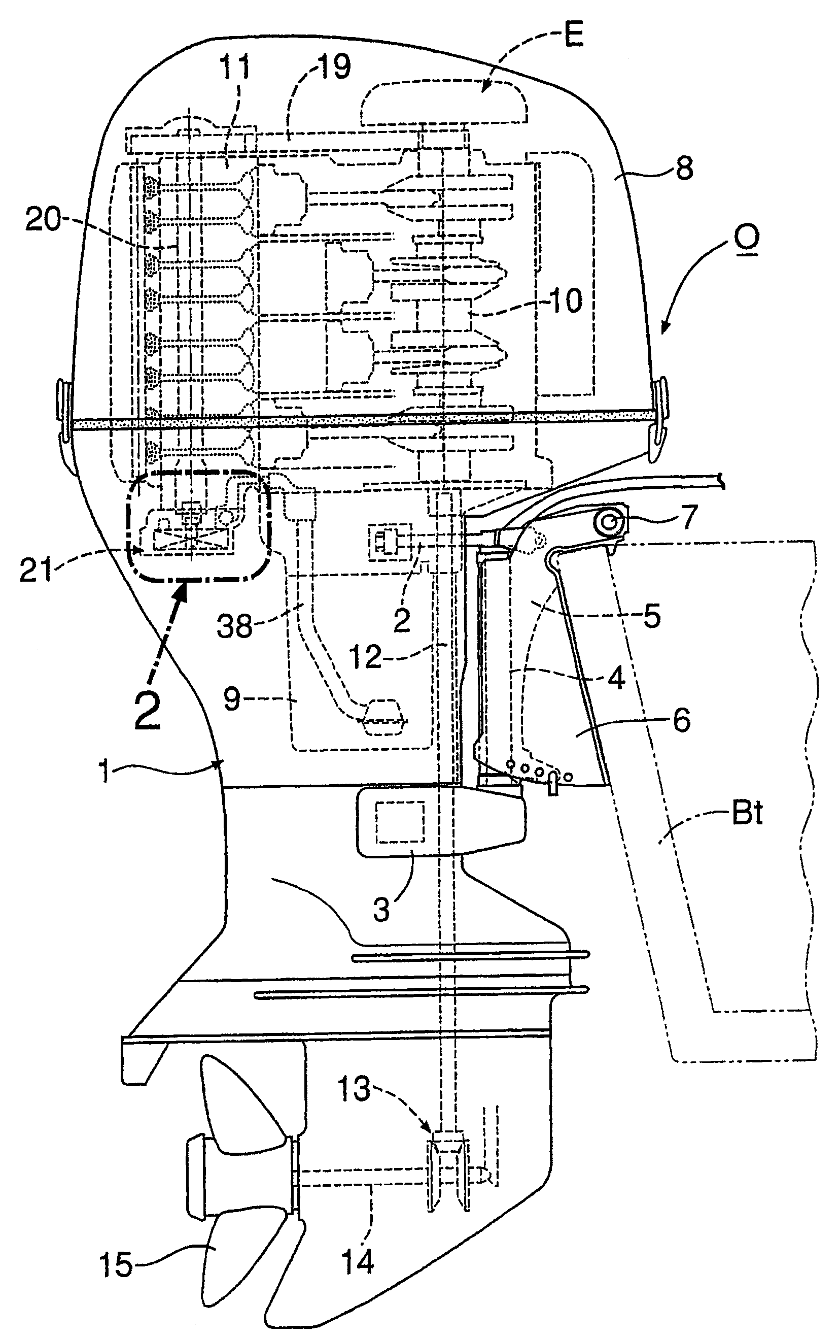
[0018] First of all, in figure 1 In the case 1 of the outboard motor O, a vertical rotating shaft 4 is arranged directly in front of the casing 1. The rotating shaft 4 is mounted on the casing 1 via the upper arm 2 and the rear arm 3, and the rotating shaft 4 is supported as The rotatable rotating shell 5 is connected to a tailstock 6 clamped on a transom Bt of the ship body via a horizontal inclined shaft 7. Therefore, the housing 1 can be turned left and right around the rotation axis 4 and can be tilted up and down around the tilt axis 7. A water-cooled 4-stroke engine E covered by a removable engine cover 8 is mounted on the upper part of the casing 1.

[0019] In this engine E, the crankshaft 10 placed in the longitudinal direction is close to the rotating shaft 4, and the cylinder head 11 is loaded toward the rear. In the housing 1 are arranged a longitudinally placed ...


PUM


Abstract

The invention provides a pump driving device of an engine, the pump driving device of the engine controls the pump (21) installed on the engine main body (11) through the valve camshaft (20) supported on the engine main body (11). The pump shaft (32) is driven. On one end of the camshaft, the bolt (23) that passes through the pulse rotor (22) and is screwed on the camshaft is used to fix the pulse rotor. Fitting parts (23c, 32a) for mutual fitting and torque transmission are formed on the pump shaft, and the fitting part on the bolt side is formed by a corner hole (23c) for wrench fitting formed on the head part (23a) of the bolt; The fitting portion on the pump shaft side is constituted by a corner shaft portion (32a) formed at one end portion of the pump shaft. In this way, a relatively large drive torque can be transmitted from the camshaft to the pump shaft without any reduction in the effective bearing surface of the journal of the camshaft.

Description

Technical field [0001] The present invention relates to an improvement of a pump drive device of an engine, which drives a pump shaft of a pump mounted on the engine body through a camshaft for a valve supported on the engine body. Background technique [0002] The pump driving device of this engine is known as disclosed in the specification of Japanese Publication No. 56-27367. [0003] However, in the conventional pump drive device, a drive pin that crosses the journal is mounted on the journal of the camshaft supported in the bearing hole of the engine body, and the drive pin is formed on the pump shaft of the pump. The notch groove where the drive pin engages transmits the rotation of the camshaft to the pump shaft through these drive pins and notch grooves. However, in order to ensure a larger effective support area on the above-mentioned journal portion of the camshaft, the drive cannot be driven The pin mounting hole is formed relatively large, so it is difficult to use a ...

Claims


Application Information

Patent Timeline
Patent Type & Authority Patents(China)
IPC IPC(8): F01M1/02
Inventor 坪内方则
Owner HONDA MOTOR CO LTD
Why Eureka
Try Eureka