Pump driving device in engine

A driving device and engine technology, which is applied in the direction of pressure lubrication of lubricating pumps, etc., can solve the problems of large installation holes for driving pins, unsuitable driving, and difficulty in using driving pins, and achieve the effects of simplified structure, reduced cost, and improved durability

Inactive Publication Date: 2007-12-05
HONDA MOTOR CO LTD
View PDF1 Cites 2 Cited by
  • Summary
  • Abstract
  • Description
  • Claims
  • Application Information

AI Technical Summary

Problems solved by technology

[0003] However, in the conventional pump driving device, a drive pin crossing the journal portion is installed on the journal portion of the camshaft supported in the bearing hole of the engine main body, and a drive pin corresponding to the shaft portion of the pump is formed on the pump shaft. The no...

Method used


Image

  • Pump driving device in engine
  • Pump driving device in engine
  • Pump driving device in engine

Examples


Embodiment Construction

[0023] Preferred embodiments of the present invention are described below with reference to the accompanying drawings.

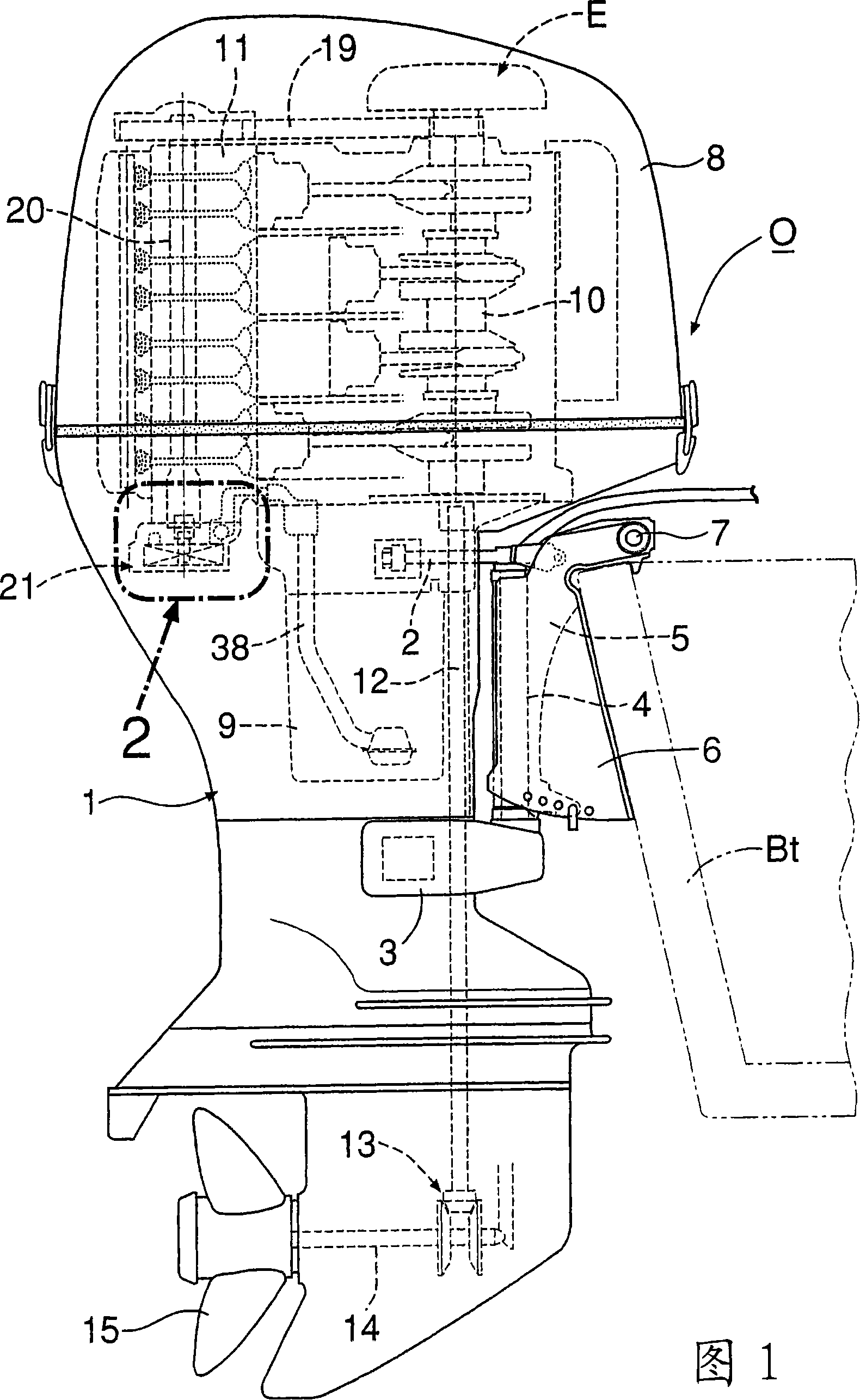
[0024] First, in FIG. 1 , a rotating shaft 4 in a vertical direction is disposed directly in front of the housing 1 of the outboard motor O, and the rotating shaft 4 is mounted on the housing 1 via the upper arm 2 and the rear arm 3 . The rotary shaft 4 is rotatably supported by a rotary housing 5 , and is connected to a tailstock 6 clamped to a transom Bt of the hull via a horizontally inclined shaft 7 . Therefore, the casing 1 can be turned left and right around the rotation axis 4 and can be tilted up and down around the tilt axis 7 . A water-cooled 4-stroke engine E covered by a detachable engine cover 8 is mounted on the upper portion of the casing 1 .

[0025] This engine E is loaded with a crankshaft 10 positioned vertically close to the rotary shaft 4 and with a cylinder head 11 facing rearward. A longitudinally placed output shaft 12 driven by the...


PUM


Abstract

To transmit large driving torque to a pump shaft from a camshaft, without substantially reducing an effective support surface of a journal part of the camshaft.The pump driving device in an engine drives the pump shaft 32 of a pump 21 installed in an engine body 11 by the camshaft 20 for a valve system supported by the engine body 11. While threadably attaching a bolt 23 having a head part 23a with a square hole 23c to one end part of the camshaft 20, a square shaft part 32a fitted to the square hole 23c is formed in one end part of the pump shaft 32, and the pump shaft 32 is driven from the camshaft 20 via these square hole 23c and square shaft part 32a.

Description

technical field [0001] The present invention relates to an improvement of an engine pump driving device that drives a pump shaft of a pump mounted on an engine body through a valve camshaft supported on the engine body. Background technique [0002] The pump driving device for this engine is known as disclosed in Japanese Patent Publication No. Sho 56-27367. [0003] However, in this conventional pump driving device, a drive pin crossing the journal portion is installed on the journal portion of the camshaft supported in the bearing hole of the engine main body, and a shaft corresponding to the shaft portion of the pump is formed on the pump shaft. The notched grooves where the drive pins engage transmit the rotation of the camshaft to the pump shaft through these drive pins and the notched grooves. Since the pin mounting hole is formed large, it is difficult to use a large-diameter drive pin, and thus it is not suitable for driving a large-scale pump with a large load. C...

Claims


Application Information

Patent Timeline
IPC IPC(8): F01M1/02
Inventor 坪内方则
Owner HONDA MOTOR CO LTD
Why Eureka
Try Eureka