LCD and backlight module thereof

A backlight module and light source technology, applied in static indicators, instruments, optics, etc., can solve problems such as uneven optical effects, influences, defects, etc., and achieve good display quality and uniform optical quality

Active Publication Date: 2009-10-21
HANNSTAR DISPLAY CORPORATION
View PDF4 Cites 0 Cited by
  • Summary
  • Abstract
  • Description
  • Claims
  • Application Information

AI Technical Summary

Problems solved by technology

Therefore, at the junction of two adjacent light guide plates, there will be uneven optical effects, and even obvious dark lines will be produced.
As a result, the display screen of the liquid crystal display will be directly affected by adverse effects.

Method used


Image

  • LCD and backlight module thereof
  • LCD and backlight module thereof
  • LCD and backlight module thereof

Examples


Embodiment Construction

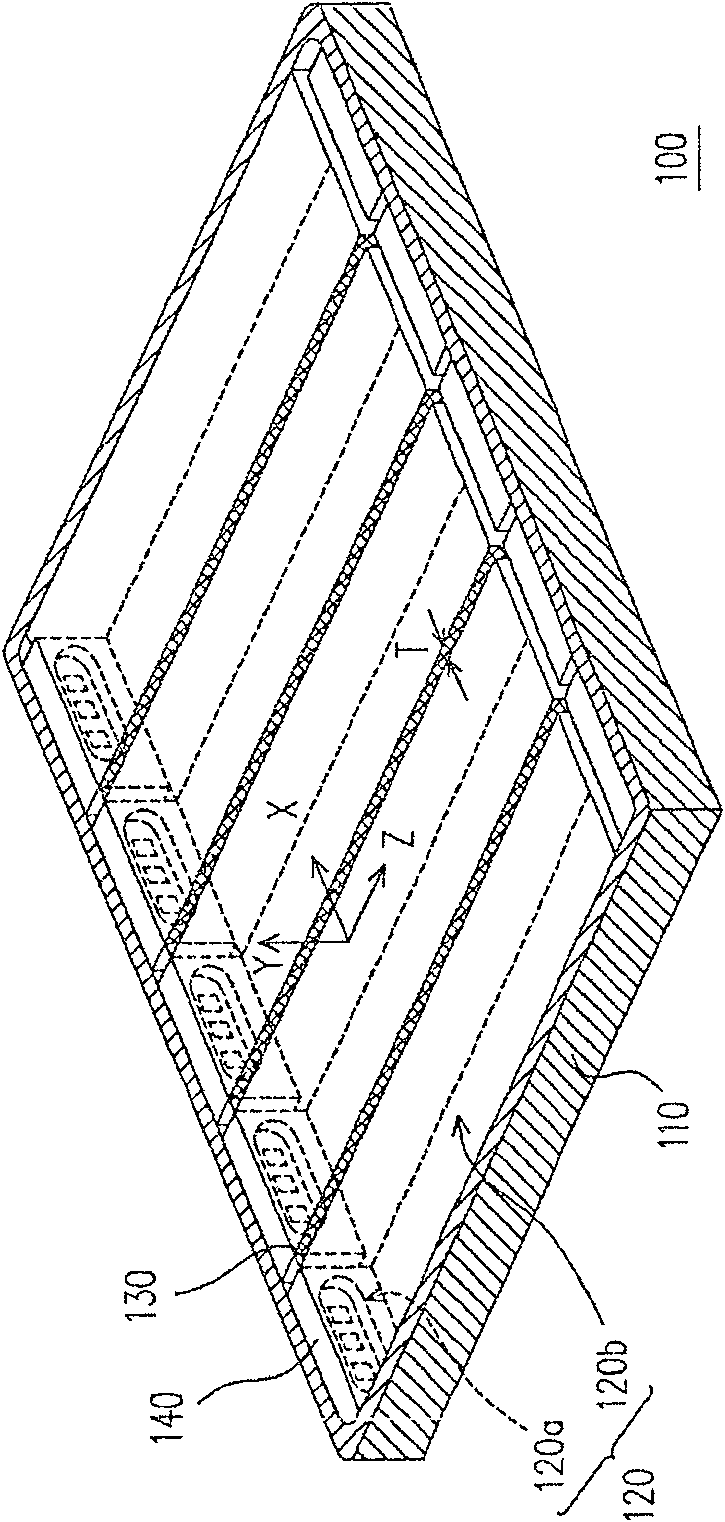
[0023] Figure 1A is an implementation schematic diagram of one of the backlight modules according to the present invention. Please refer to Figure 1A , the backlight module 100 of this embodiment includes a frame 110 , a plurality of light guide plates (LGP) 120 , a plurality of high refractive index media 130 and a plurality of light sources 140 . Wherein, the light guide plates 120 are disposed in the outer frame 110, and each light guide plate 120 has at least one light incident surface 120a and one light exit surface 120b. Such as Figure 1A Each light guide plate 120 shown has two light incident surfaces 120a and light output surfaces 120b facing each other. Of course, those skilled in the art should know Figure 1A The light guide plate 120 shown here is only for illustration, and the type of the light guide plate 120 is not intended to be limited.

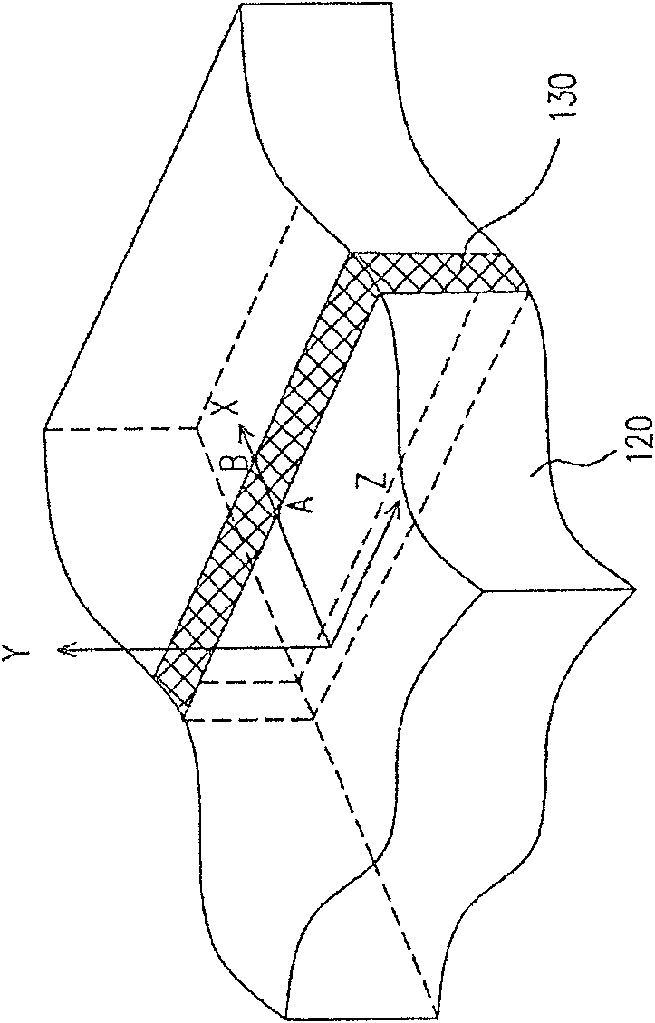
[0024] In addition, the high refractive index medium 130 is respectively disposed between two adjacent light guide plat...


PUM

PropertyMeasurementUnit
thicknessaaaaaaaaaa
refractive indexaaaaaaaaaa

Abstract

A backlight module includes an outer frame, a plurality of light guide plates, a plurality of high refractive index media and a plurality of light sources. Wherein, the light guide plate is arranged in the outer frame, and each light guide plate has at least one light incident surface and one light exit surface. In addition, the high refractive index medium is respectively arranged between two adjacent light guide plates. In addition, the light sources are respectively arranged beside the light incident surface of the light guide plate.

Description

technical field [0001] The invention relates to a display and its backlight module, and in particular to a liquid crystal display with multiple light guide plate structures and its backlight module. Background technique [0002] In general displays, since the liquid crystal display panel itself does not have the function of emitting light, a backlight module must be arranged under the liquid crystal display panel to provide a surface light source, so that the liquid crystal display panel can achieve the purpose of displaying images. In order to further improve the quality of the display image, a scanning backlight module (Scan backlight module) appears on the market. [0003] Specifically, the scanning backlight module is mainly composed of a plurality of light guide plates (LGP) and a plurality of light sources. Wherein, the light emitted by the light source is transmitted to the liquid crystal display panel through the light guide plate, so as to provide the light source ...

Claims


Application Information

Patent Timeline
Patent Type & Authority Patents(China)
IPC IPC(8): G02F1/13357G02F1/133G02F1/1335
Inventor 吴昭慧张之礼
Owner HANNSTAR DISPLAY CORPORATION
Why Eureka
Try Eureka