Improved tunnel smoke discharging method and tunnel fume discharging system with independent fume discharging device

A technology of smoke exhaust system and smoke exhaust device, which is applied in mine/tunnel ventilation, earthwork drilling, mining equipment, etc. It can solve problems such as waste, affecting the efficiency of smoke exhaust, and narrow cross-section, so as to improve effectiveness and economy Guaranteed safety and improved safety

Active Publication Date: 2009-11-04
ZHEJIANG PROVINCIAL INST OF COMM PLANNING DESIGN & RES CO LTD
View PDF5 Cites 0 Cited by
  • Summary
  • Abstract
  • Description
  • Claims
  • Application Information

AI Technical Summary

Problems solved by technology

[0005] 2. If it is necessary to ensure that the area of ​​the wind crossing for normal operation is not reduced, it is necessary to expand the section of the main tunnel, which will increase the civil construction cost of the tunnel;
[0006] 3. The smoke exhaust duct is set on the vault of the main tunnel, with a narrow section and a flat shape, which may affect the efficiency of smoke exhaust, and may bring certain difficulties to maintenance and repair;
[0007] 4. In the double-pipe one-way traffic tunnel, two independent smoke exhaust ducts and matching smoke exhaust dampers need to be installed in the two main tunnels, that is, the smoke exhaust ducts cannot be shared by the two tunnels, which is wasteful;
[0008] 5. The structural design and construction of the connection node between the smoke exhaust duct and the main tunnel are difficult

Method used


Image

  • Improved tunnel smoke discharging method and tunnel fume discharging system with independent fume discharging device
  • Improved tunnel smoke discharging method and tunnel fume discharging system with independent fume discharging device
  • Improved tunnel smoke discharging method and tunnel fume discharging system with independent fume discharging device

Examples


Embodiment Construction

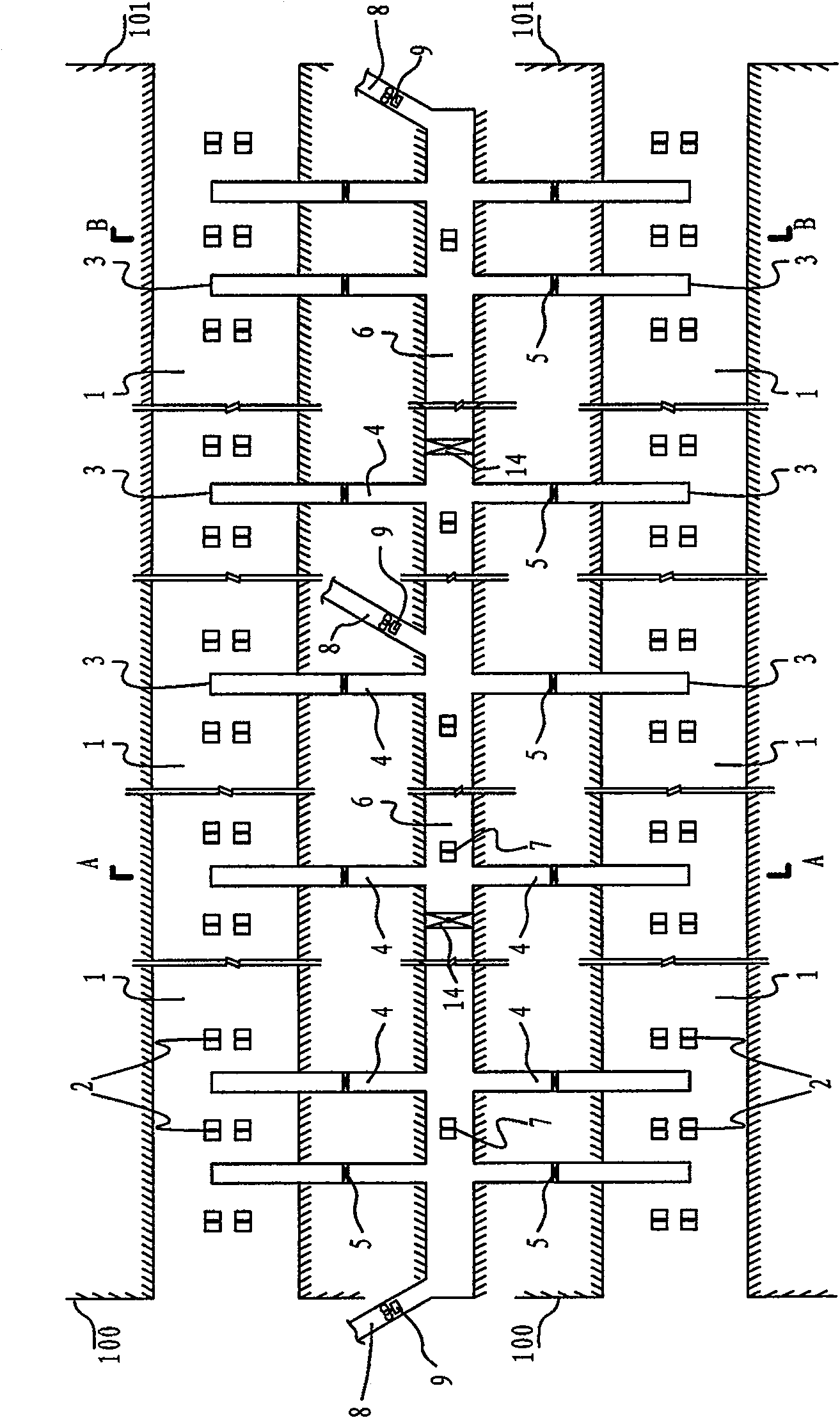
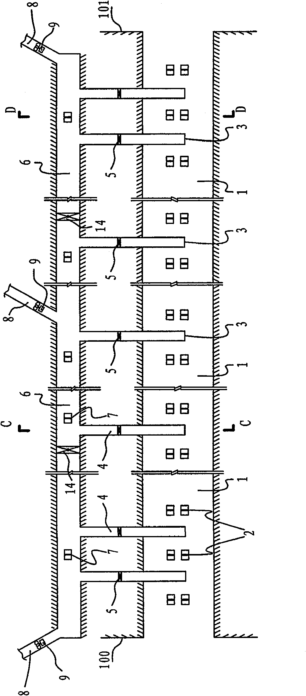
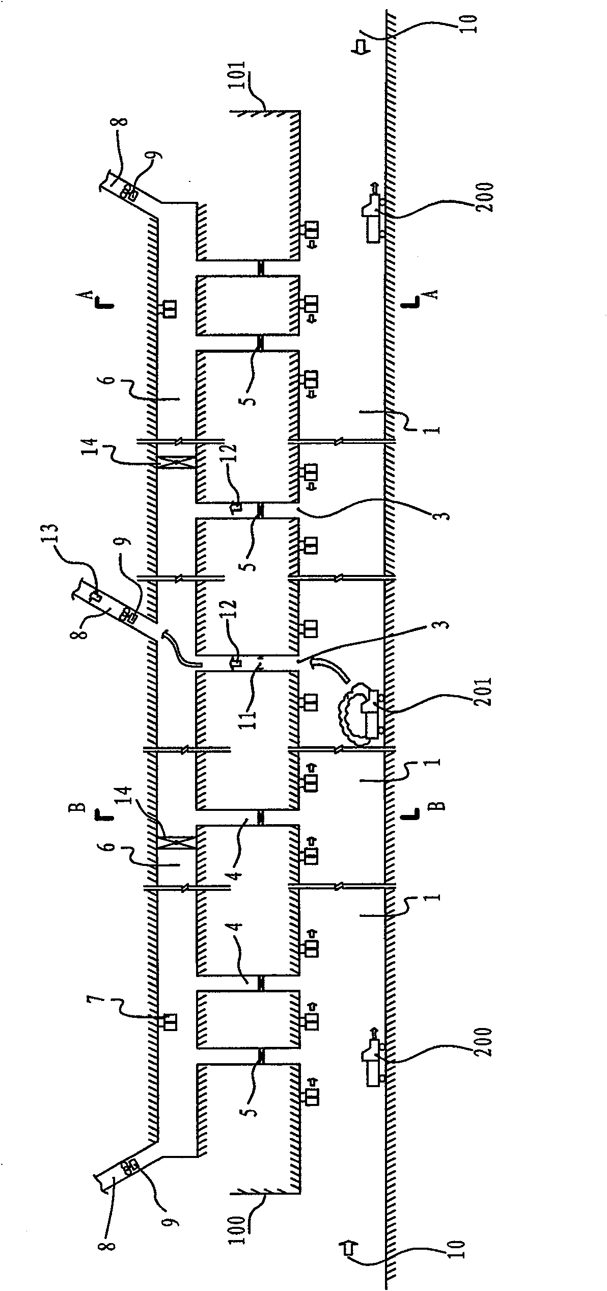
[0050] see figure 1 , 2 , the main tunnel has two ports, the tunnel entrance 100 and the tunnel exit 101. In practical applications, even if the tunnel has multiple ports, the smoke exhaust system is still applicable. The principles of ventilation and smoke exhaust are the same, but the specific arrangement of the equipment is different.

[0051] The whole main tunnel constitutes a tunnel main air duct (1), and several main air duct jet fans (2) are installed on the top, side or other positions of the tunnel as required in the tunnel. The independent smoke exhaust device includes a smoke exhaust duct (6), a smoke exhaust duct fan (7) and a smoke exhaust damper (14) provided as required, and a smoke exhaust port (3) arranged above the main air duct section of the tunnel , the smoke exhaust cross passage (4) connecting the tunnel smoke exhaust outlet (3) and the smoke exhaust air duct (6), the smoke exhaust damper (5) arranged in the smoke exhaust cross passage (4), and the smo...


PUM


Abstract

The invention discloses an independent smoke exhaust method for a tunnel, which includes: (1) setting a smoke exhaust air duct with an independent structure outside the main tunnel section, and setting exhaust air ducts at intervals along the longitudinal axis of the tunnel above the main air duct section of the tunnel; The smoke outlet and the smoke exhaust outlet are connected with the smoke exhaust duct by the smoke exhaust cross duct, the smoke exhaust damper is arranged on the smoke exhaust cross duct, and the smoke exhaust fan is installed in the smoke exhaust connecting air duct; (3) When a fire occurs in the tunnel and smoke needs to be exhausted, open the smoke exhaust damper near the smoke source, and the smoke will pass through the smoke exhaust duct, The smoke exhaust connection duct is discharged from the tunnel to the outside of the cave. The invention also discloses a tunnel smoke exhaust system implementing the above method, and the smoke exhaust system is provided with an independent smoke exhaust device. The invention simplifies the complexity of the control of the smoke exhaust system, reduces the normal operation energy consumption, improves the smoke exhaust efficiency, and is beneficial to structural design and construction treatment.

Description

technical field [0001] The invention relates to an improved tunnel smoke exhaust method and a tunnel smoke exhaust system with an independent smoke exhaust device, which are mainly used for smoke exhaust in the case of fire in the tunnel. Background technique [0002] In the existing longitudinal ventilation technology, the problem of independent smoke exhaust in case of fire is not fully considered, and the smoke flows, spreads, and is discharged along the longitudinal direction of the tunnel. It is difficult to ensure the safe escape of personnel for extra-long highway tunnels, especially when there is a large passenger flow; for single-hole two-way traffic fire conditions, secondary accidents and other fire conditions, it cannot effectively solve the smoke exhaust problem during the evacuation stage. In order to solve the safety problem of personnel evacuation under fire conditions in extra-long highway tunnels, and take into account the economy during normal operation, t...

Claims


Application Information

Patent Timeline
Patent Type & Authority Patents(China)
IPC IPC(8): E21F1/00E21F1/04E21F1/08
Inventor 吴德兴李伟平郑国平高翔郭宵
Owner ZHEJIANG PROVINCIAL INST OF COMM PLANNING DESIGN & RES CO LTD
Why Eureka
Try Eureka