Unlock instant, AI-driven research and patent intelligence for your innovation.
Centrifugal flow guiding intelligent speed governing hydraulic coupler body structure
What is Al technical title?
Al technical title is built by PatSnap Al team. It summarizes the technical point description of the patent document.
A technology of hydraulic coupling and intelligent speed regulation, which is applied to fluid transmission devices, belts/chains/gears, mechanical equipment, etc., which can solve the problems of insufficient utilization of working oil energy, reduced adaptability of couplings to loads, and problems of couplings. Unstable work and other problems, achieve significant economic and social benefits, save raw materials, reduce wall thickness and size
Inactive Publication Date: 2009-11-18
SHANGHAI JIAOTONG UNIV
View PDF4 Cites 0 Cited by
Summary
Abstract
Description
Claims
Application Information
AI Technical Summary
This helps you quickly interpret patents by identifying the three key elements:
Problems solved by technology
Method used
Benefits of technology
Problems solved by technology
The labyrinth oil seal of the coupler body structure is arranged along the axial direction of the coupler, and the centrifugal force of the working oil rotation cannot be utilized, resulting in large oil leakage, resulting in energy loss and instability of the coupler work; its working oil It is led out from the trumpet-shaped openings with a fixed number and diameter on the rotary housing. The energy of the drawn-out working oil is not fully utilized, and at the same time, the adaptability of the coupler to the load is reduced; the coupler body adopts an internal support method. In order to ensure strength, The structural size of the coupler box is relatively large
Method used
Image
Click on the blue label to locate the original text in one second.
Reading with bidirectional positioning of images and text.
Examples
Embodiment Construction
[0013] The specific implementation of the present invention will be further described below in conjunction with the accompanying drawings.
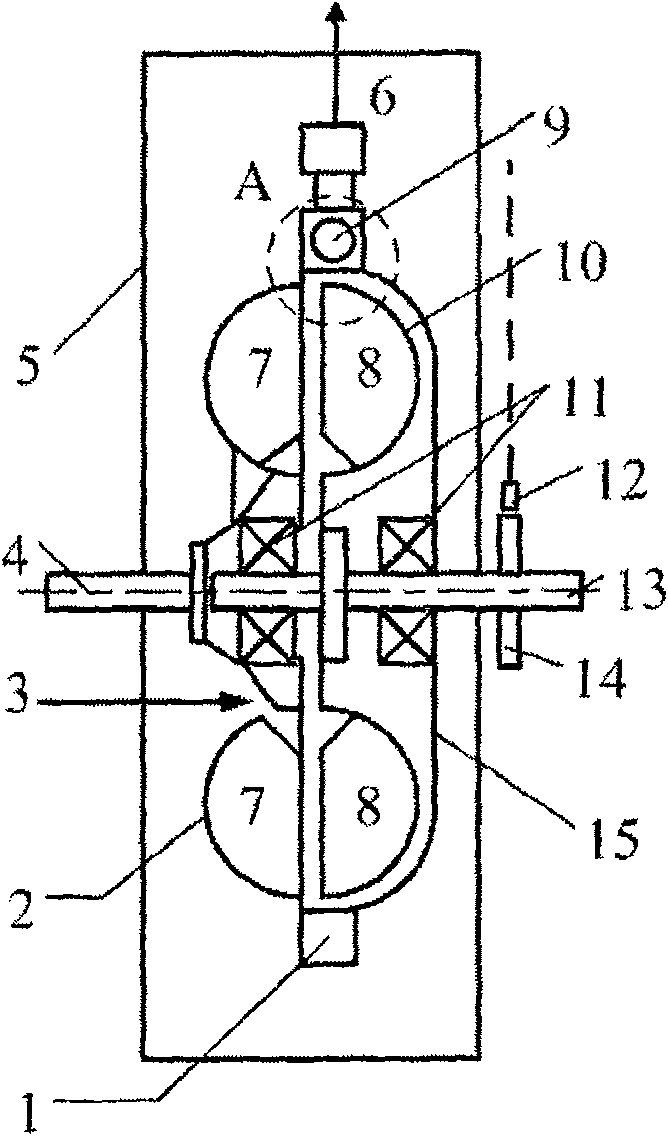
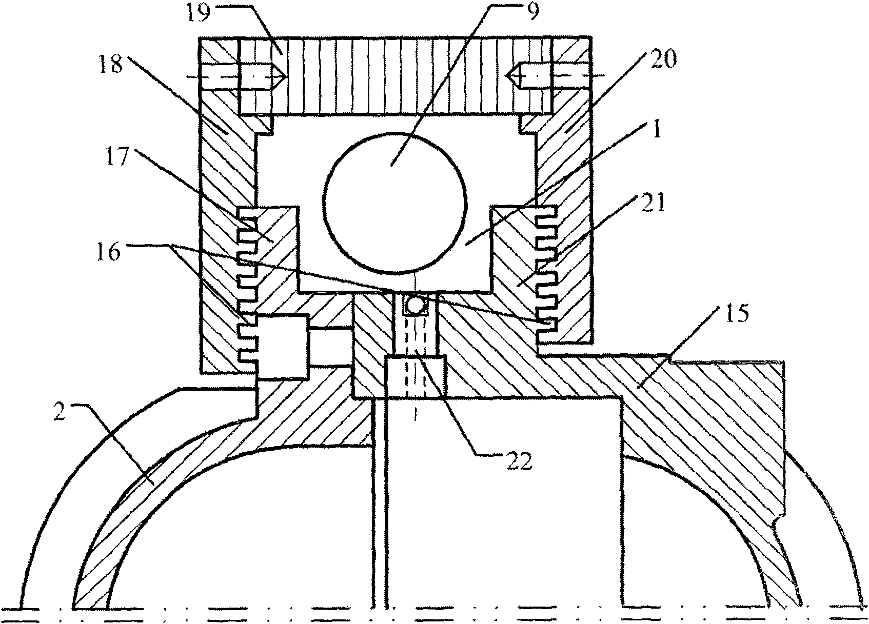
[0014] like figure 1 , 2 As shown: the present invention includes: centrifugal diversion groove 1, pump wheel 2, oil inlet connecting pipe 3, driving shaft 4, box body 5, oil outlet connecting pipe 6, turbine 10, bearing 11, speed sensor 12, slave Moving shaft 13, speed measuring gear 14, rotating case 15, labyrinth oil seal 16, pump wheel flange 17, left sealing end face 18, oil sealing ring 19, right sealing end face 20, rotating case flange 21, nozzle 22.
[0015] The driving shaft 4 is connected to the output shaft of the prime mover, the driven shaft 13 is connected to the working machine, the entire coupling body is suspended on the shaft of the prime mover and the working machine, and the pump wheel flange 17 is connected to the rotary casing flange 21 by bolts. The pump wheel method The flange 17 is integrated with the pump whee...
PUM
Abstract
The utility model relates to a body structure of a centrifugal diversion intelligent speed-regulating hydraulic coupling, which belongs to the technical fields of energy saving and hydraulic transmission. Including pump wheel, pump wheel flange, turbine, driving shaft, driven shaft, box body, oil inlet and outlet connecting pipes, speed sensor, speed measuring gear, rotary casing, rotary casing flange, nozzle, left and right sealing end faces, oil sealing ring , the present invention adopts the principle of centrifugal flow diversion. Under the action of centrifugal force, the nozzle installed on the rotary shell is used to draw out the working oil for cooling, and the number and aperture of the nozzle are determined according to the coupling model and load characteristics, and the coupling is more adaptable to the load. ;The radially arranged labyrinth oil seal greatly reduces the leakage at the seal, reduces the energy loss of the coupler, and enhances the controllability of the coupler's speed and working stability; the coupler adopts an external support method, and the box no longer bears the weight of the coupler body , it only plays the role of oil storage, its wall thickness and size are significantly reduced, the overall structure of the coupling is more compact, saving raw materials, and has significant economic and social benefits.
Description
technical field [0001] The invention relates to a speed-regulating hydraulic coupling, in particular to a body structure of a coupling body that adopts a labyrinth oil seal and a centrifugal flow diversion intelligent speed-regulating hydraulic coupling that extracts working oil from a nozzle, which belongs to energy-saving and hydraulic transmission. technology field. Background technique [0002] At present, there are many traditional speed-regulating hydraulic couplings, and their common feature is that a certain amount of working oil is filled in the working chamber of the hydraulic coupling, and the pump wheel obtains mechanical energy from the prime mover, converts it into liquid energy, flows to the turbine and Make it rotate, the turbine converts the liquid energy into mechanical energy output, and repeats itself, realizing the energy transfer from the prime mover to the working machine. Usually, the speed regulation of the speed-regulating hydraulic coupling is rea...
Claims
Application Information
Patent Timeline
Application Date:The date an application was filed.
Publication Date:The date a patent or application was officially published.
First Publication Date:The earliest publication date of a patent with the same application number.
Issue Date:Publication date of the patent grant document.
PCT Entry Date:The Entry date of PCT National Phase.
Estimated Expiry Date:The statutory expiry date of a patent right according to the Patent Law, and it is the longest term of protection that the patent right can achieve without the termination of the patent right due to other reasons(Term extension factor has been taken into account ).
Invalid Date:Actual expiry date is based on effective date or publication date of legal transaction data of invalid patent.
