Thin display device and method of pulling out display part

A technology for thin display devices and display parts, which is applied to identification devices, parts of color TVs, parts of TV systems, etc. It can solve problems such as complex structures and inability to adjust the angle of the display screen, and achieve effective transportation functions such as suppressing shaking , the effect of simply pulling out

Inactive Publication Date: 2009-12-16
SHARP KK
View PDF7 Cites 1 Cited by
  • Summary
  • Abstract
  • Description
  • Claims
  • Application Information

AI Technical Summary

Problems solved by technology

[0015] The thin TV is easy to carry indoors due to its thinning and light weight, but when it is moved, because for example, in the monitoring device described in Patent Document 1, the stand is held, etc. In the pedestal-type thin TV set described above, it is transported integrally from the main body 101 to the pedestal 103. Therefore, when the moving destination is, for example, a place such as a desk or the like that does not require the support 102 from the height of the viewing point, or Even if it is moved to a narrow installation place that interferes with the stand 103, its movement will still cause problems, and a thin TV with higher versatility that is not limited by the installation place is desired.
[0016] In addition, in the system of the monitoring device and the base device described in Patent Document 2, when placed on the base device for viewing, the angle of the display screen cannot be adjusted, and the angle adjustment functions in the elevation angle direction and the left and right directions are not provided. There are issues requiring complex structures

Method used


Image

  • Thin display device and method of pulling out display part
  • Thin display device and method of pulling out display part
  • Thin display device and method of pulling out display part

Examples


no. 1 Embodiment

[0093] A first embodiment of the present invention will be described in detail below with reference to the drawings.

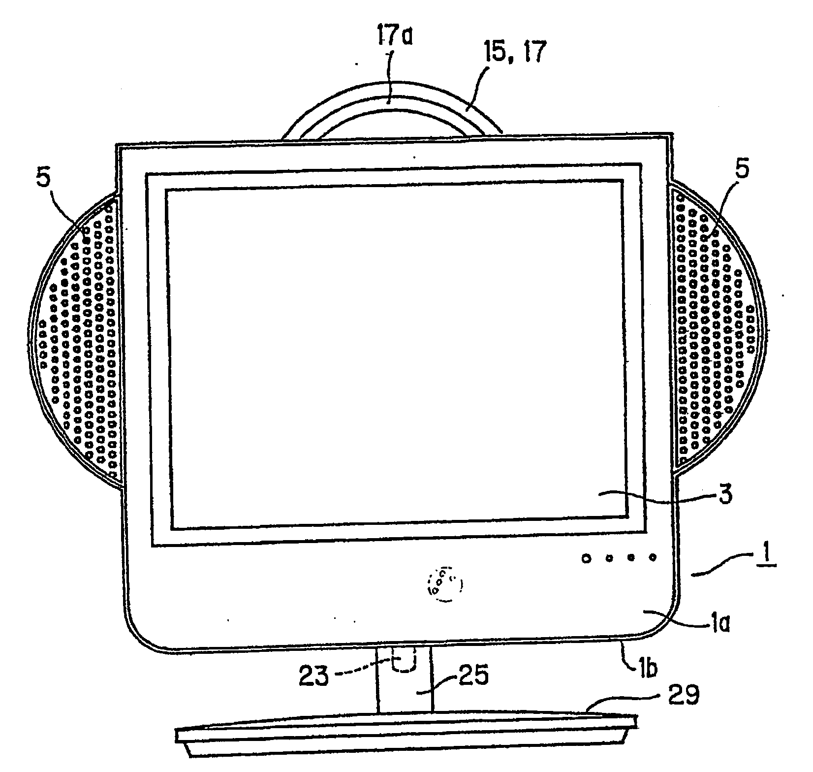
[0094] figure 1 It is the front view of the pedestal-type thin TV of this embodiment. In addition, in the embodiment, as the display device 1 for displaying information such as images and images, a liquid crystal display is used as an example, and various thin display devices such as plasma displays and organic EL (electroluminescence) can also be used.

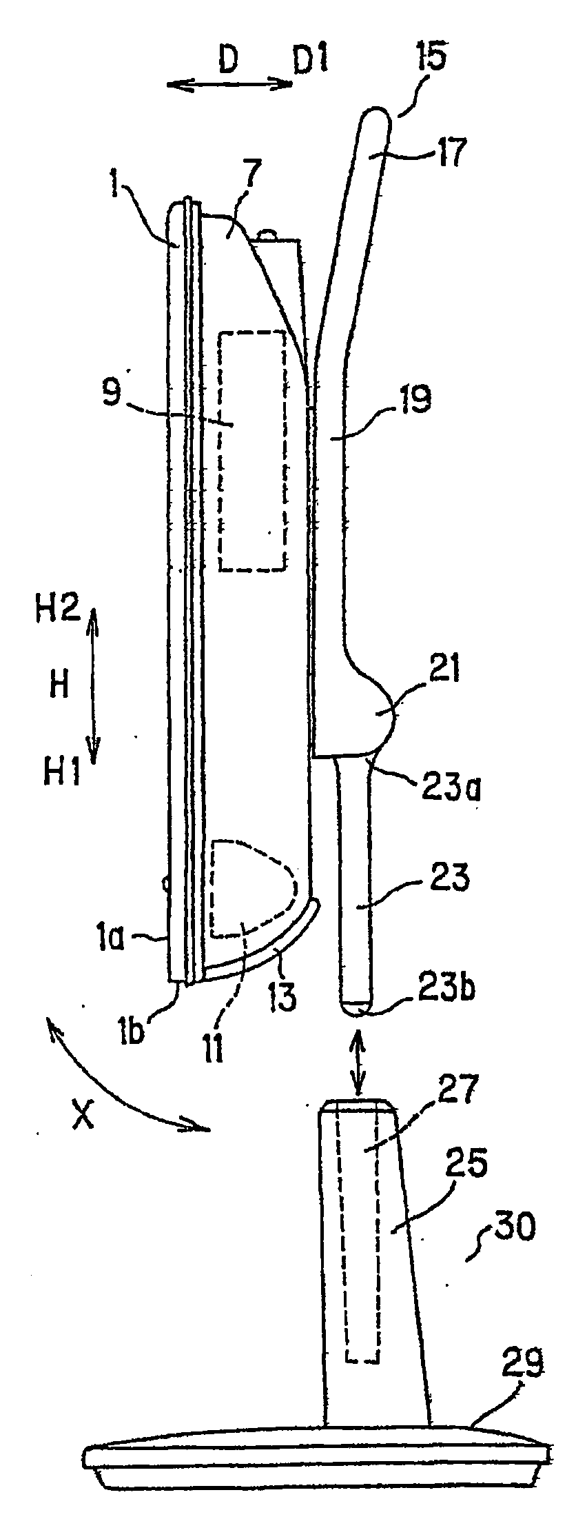
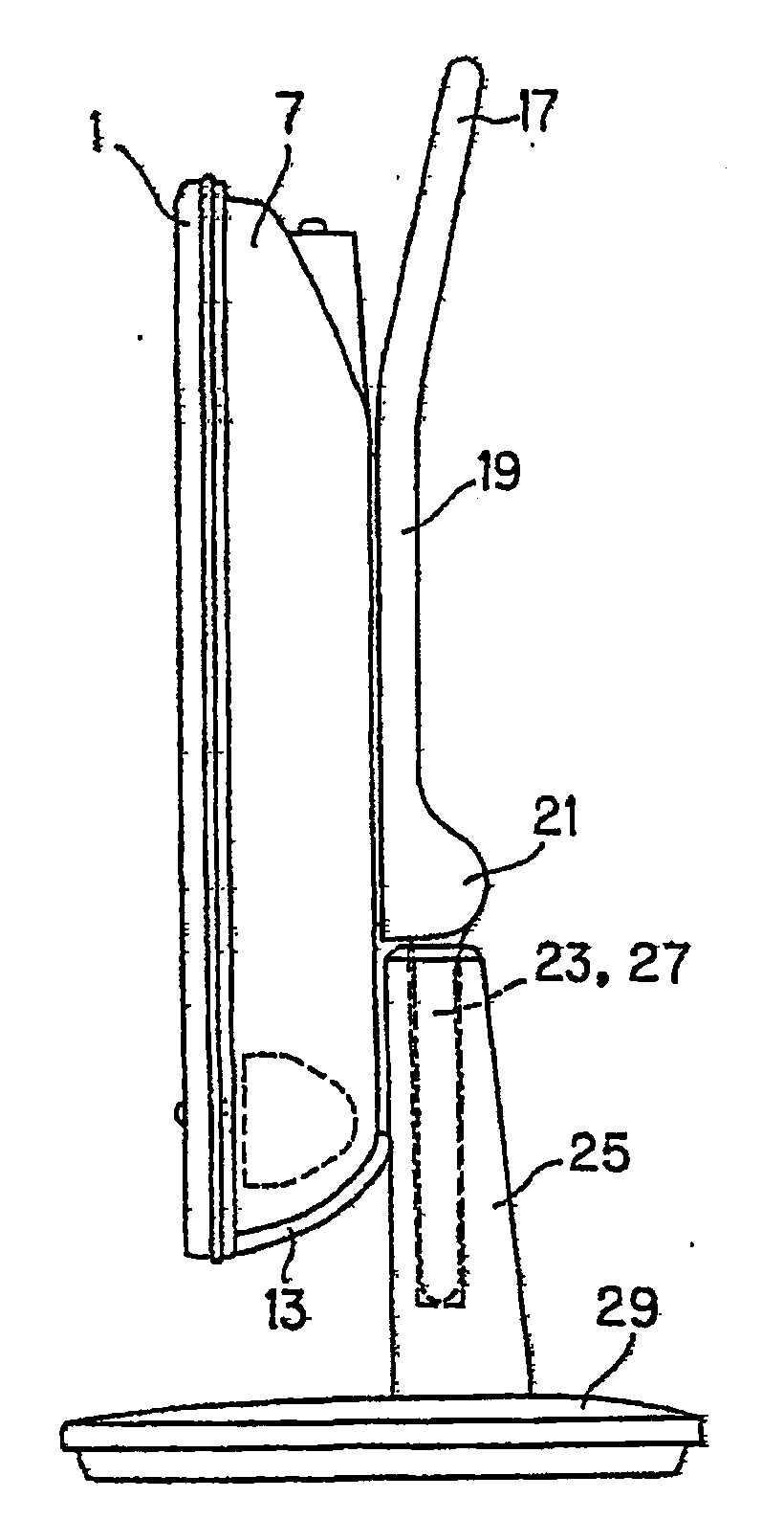
[0095]The pedestal-type thin television has a display device 1 , a connecting body 15 , and a pedestal column portion 30 composed of a column 25 and a pedestal 29 . The connecting body 15 is installed on the display device 1, and the connecting body 15 is detachable on the pillar 25 fixed on the support 29. And the display device 1 is supported by the support column part 30. In the second use state in which the support column part 30 is not used, the connecting body 15 itself is used as a support column fo...

no. 2 Embodiment

[0140] Next, a second embodiment of the present invention will be described in detail with reference to the drawings. Parts that are the same as those in the above-mentioned configuration are denoted by the same reference numerals, and description thereof will be omitted, and the description will focus on parts that are different from the above-mentioned embodiments. Roughly speaking, the difference from the above-mentioned embodiment is that the cross-sectional shape of the seat and connecting portion is changed from a circular shape to a substantially rectangular shape ( Figure 9 , Figure 14 ), change the shape of the pillar according to the shape change of the support and connecting part ( Figure 9 , Figure 14 ), the support can be rotated relative to the support in the horizontal direction Y ( Figure 9 ), and on the grip portion 17, a remote control clip 51 ( Figure 15 ~ Figure 17 ), as detailed below.

[0141] The support and connecting part 35 of the present e...

no. 3 Embodiment

[0160] Next, a third embodiment of the present invention will be described in detail with reference to the drawings. Parts that are the same as those in the above-mentioned configuration are denoted by the same reference numerals, and description thereof will be omitted, and the description will focus on parts that are different from the above-mentioned second embodiment. Roughly speaking, the difference from the above-mentioned second embodiment is that the holder and connecting portion are provided with a drop-off preventing recess 59 and a protrusion 61 for restricting the insertion direction, and the length is made to be parallel to the liquid crystal display 3 . , changed to the length below (including the same length) to the length of the bottom side 1b of the front side frame 1a of the display device 1 ( Figure 20 , Figure 21 ), set the anti-off mechanism of the support and connecting part on the pillar ( Figure 20 ~ FIG. 24 ), and in order to limit the elevation a...


PUM


Abstract

A display device such as a flat-screen TV that is easy to install, remove and transport a display part from a stand member and is not limited by the installation place of the display part. The stand-type thin TV has a display device (1), a connecting body (15 ), pillar (25) and support (29). By connecting body (15) being installed on the display device (1), on the pillar (25) that is fixed on bearing (29), be formed with the connecting body (15) that detachable freely, when using pillar (25) and In the first use state of the support (29), the connecting body (15) is inserted into the support (25), and in the second use state of not using the support (25) and the support (29), the connecting body (15) Used as a stand by itself.

Description

[0001] The patent application of the present invention is PCT / JP2003 / 017001, the international application date is December 26, 2003, the application number entering the Chinese national stage is 200380108195.1, and the name is "thin display device and method for pulling out its display part" "A divisional application of the invention patent application. technical field [0002] The present invention relates to a thin display device which can be used in various usage forms and a method for pulling out the display part thereof. Background technique [0003] In a conventional TV set using a cathode ray tube, in order to maintain the display screen of the TV set at a predetermined height consistent with the height and direction of the line of sight of the person watching the TV set, it is placed on a TV set that can bear the weight of the TV set. The shelves and cabinets that have been used are put up for use. [0004] On the other hand, recently, a thin-type television in whi...

Claims


Application Information

Patent Timeline
Patent Type & Authority Patents(China)
IPC IPC(8): H04N5/64G09F9/00F16M11/00F16M13/02G06F1/16
Inventor 渡边隆雄
Owner SHARP KK
Why Eureka
Try Eureka