
Fixing device and control method thereof

A fixing device and fixing block technology, used in workpiece clamping devices, semiconductor/solid-state device manufacturing, manufacturing tools, etc., can solve problems such as increasing labor costs, inability to detect whether the clamping has reached a predetermined position, crushing glass substrates, etc. , to achieve the effect of reducing accidents, saving costs and reducing power consumption

Inactive Publication Date: 2010-01-20
HONG FU JIN PRECISION IND (SHENZHEN) CO LTD +1
View PDF3 Cites 0 Cited by
  • Summary
  • Abstract
  • Description
  • Claims
  • Application Information

AI Technical Summary

Problems solved by technology

[0004] First of all, when adjusting the clamping force of the fixing device, it is necessary to replace the spring and adjust the pressure of the air valve, which increases the labor cost virtually; in addition, the use of pneumatic components as the fixing device cannot detect whether the clamping has reached the predetermined position. Careful you will crush the glass substrate

Method used


Image

  • Fixing device and control method thereof
  • Fixing device and control method thereof
  • Fixing device and control method thereof

Examples


Embodiment Construction

[0014] The embodiments of the present invention will be further described in detail below in conjunction with the accompanying drawings.

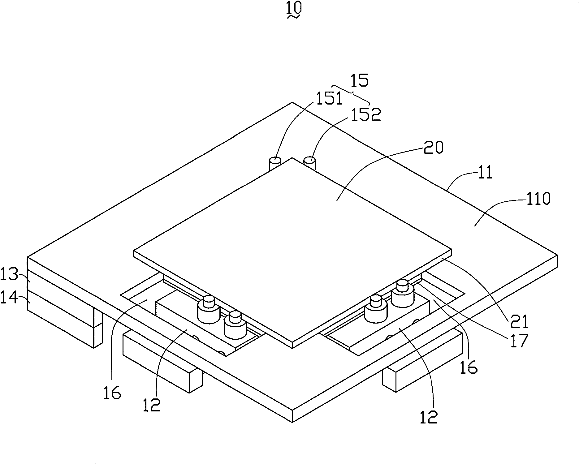
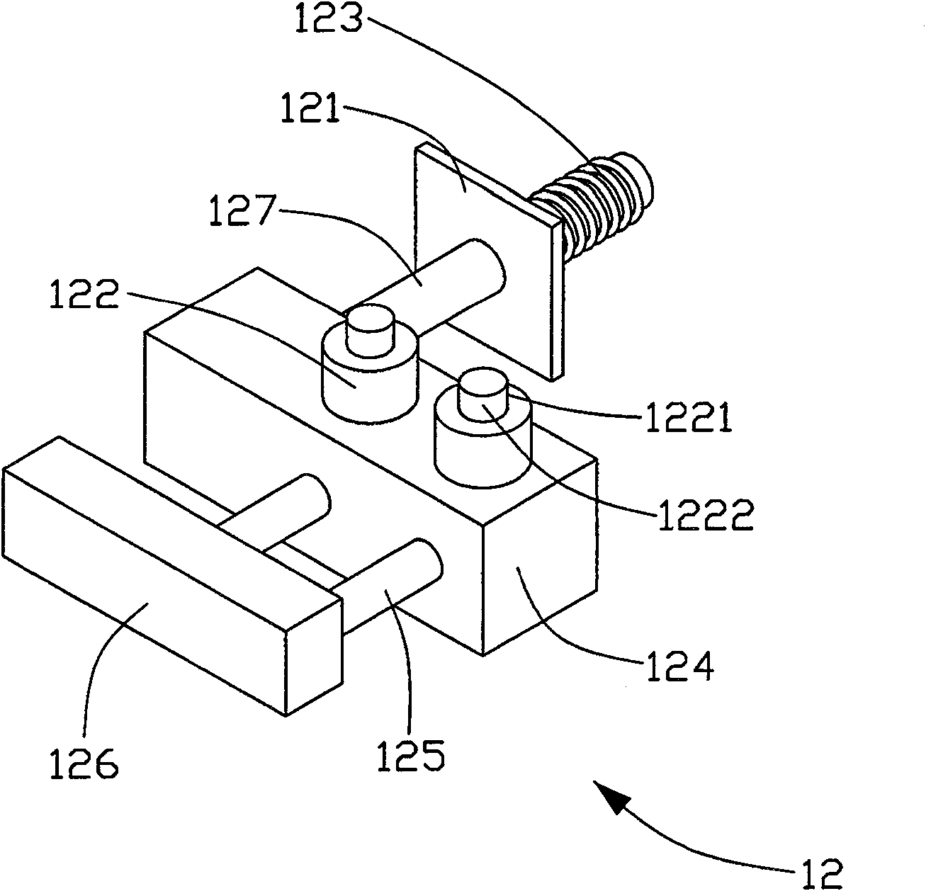
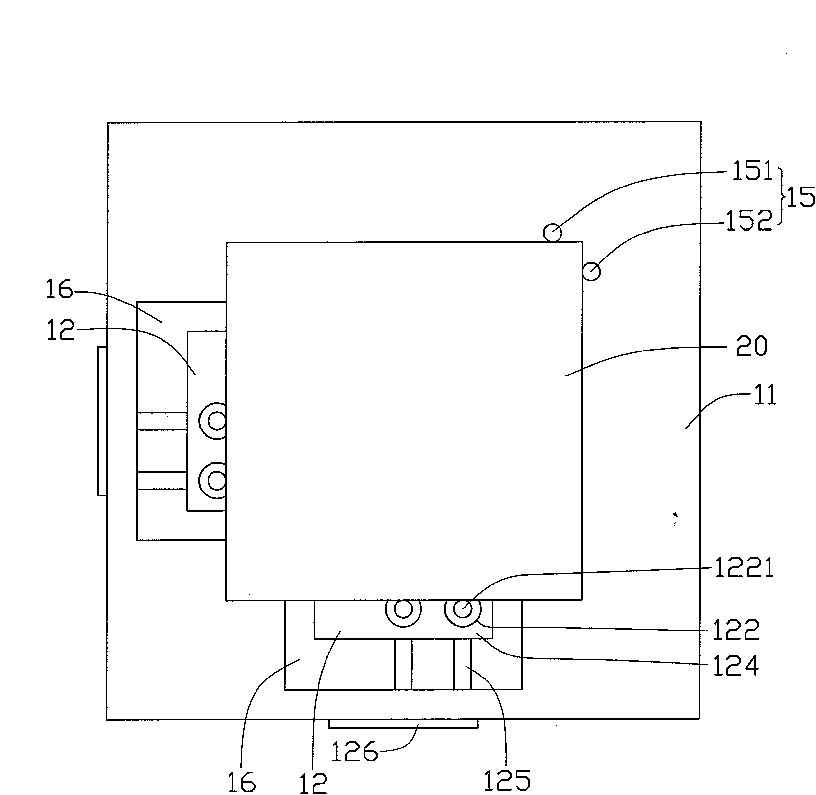
[0015] see Figure 1 to Figure 3 , the fixing device 10 provided by the embodiment of the present invention includes a support plate 11 , a plurality of clamps 12 , a first control unit 13 and a second control unit 14 .

[0016] The support plate 11 is used to support the substrate 20 , and positioning pins 15 , such as a first positioning pin 151 and a second positioning pin 152 , are disposed on the edge of the upper surface 110 .

[0017] The plurality of clamps 12 respectively include a permanent magnet 121 , a plurality of resisting pieces 122 , an electric coil 123 and an iron core 127 . The permanent magnet 121 is disposed opposite to the electric coil 123 , the iron core 127 is disposed in the extension direction of the center of the electric coil 123 , and the iron core 127 and the plurality of resisting pieces 122 keep moving syn...


PUM


Abstract

The invention relates to a fixing device including a support plate for supporting a basal plate; a plurality of clamps, each of which includes an electric coil; a first control unit, which is electrically connected with the electric coils and includes a pulse-width modulation (PWM) controller for controlling the strength of the clamping force of each clamp via programming; and a second control unit, which is used for judging whether the basal plate clamped by the clamps reaches the pre-calculated position according to the detected reverse phase electromotive force generated on each electric coil. In addition, the invention also relates to a fixing device control method adopting the fixing device. The fixing device and the fixing device control method arrange the first and the second control units to adjust the clamping force and detect whether the clamping reaches the pre-calculated position, thereby saving cost, lowering power consumption and reducing accident of basal plate cracking.

Description

technical field [0001] The invention relates to a fixing device and a control method thereof, in particular to a fixing device for clamping a flat panel display substrate and a control method thereof. Background technique [0002] In the general flat-panel display manufacturing process, pneumatic components, such as cylinders, are currently used as fixing devices to clamp and position the glass substrate. [0003] However, the use of pneumatic components as fixtures has the following drawbacks: [0004] First of all, when adjusting the clamping force of the fixing device, it is necessary to replace the spring and adjust the pressure of the air valve, which increases the labor cost virtually; in addition, the use of pneumatic components as the fixing device cannot detect whether the clamping has reached the predetermined position. Be careful and you will crush the glass substrate. [0005] The purpose of the present invention is to overcome the above defects and provide a f...

Claims


Application Information

Patent Timeline
Patent Type & Authority Patents(China)
IPC IPC(8): B25B11/00H01L21/68
Inventor 陈健宏郑振兴
Owner HONG FU JIN PRECISION IND (SHENZHEN) CO LTD
Learn More