Infrared laser traffic information acquisition instrument

A technology of traffic information collection and infrared laser, which is applied in the field of laser technology application, can solve the problems of affecting the appearance of the road environment, easy to miss inspection, and high cost, and achieve the effect of low overall cost, easy installation, and reduced aesthetics

Inactive Publication Date: 2010-02-10
ZHONGJIAO YUANZHOU TRAFFIC TECH GROUP +1
View PDF6 Cites 0 Cited by
  • Summary
  • Abstract
  • Description
  • Claims
  • Application Information

AI Technical Summary

Problems solved by technology

The advantage of this method is that the model classification accuracy is high, the response is fast, and it is less affected by the weather and the environment; It is easy to miss detection when driving away from the middle of the lane. For example, multiple laser range finders are used at the front and rear of each lane. Although the problem of vehicle missed detection can be solved, the cost is too high
Moreover, this method, like the ultrasonic detection method, also needs to be installed on the "gantry frame", which has high auxiliary costs and affects the beauty of the road environment, and is not suitable for the situation where the equipment layout density is high
Therefore, this laser traffic information collection device has many defects, which are limited in practical popularization and application.

Method used


Image

  • Infrared laser traffic information acquisition instrument
  • Infrared laser traffic information acquisition instrument
  • Infrared laser traffic information acquisition instrument

Examples


Embodiment 1

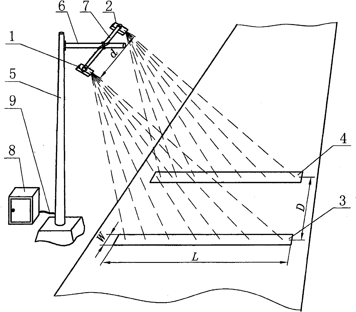
[0024] Example 1 (see figure 1 , 2 ):

[0025] figure 1 In order to be applied to a single lane, the present embodiment includes a roadside bracket, first and second infrared laser sensors 1, 2, a controller 8, and corresponding first and second infrared laser sensors located on the road. two parallel first and second reflective strips 3 and 4 perpendicular to the direction of the lane; the first and second infrared laser sensors 1 and 2 are fixed on the cross bar 7 on the bracket, and the first and second infrared laser sensors The distance d between the two infrared laser sensors 1 and 2 is equal to the distance D between the first and second reflective tapes 3 and 4 . The first and second infrared laser sensors 1 and 2 are connected to the controller 8 through a cable 9 ;

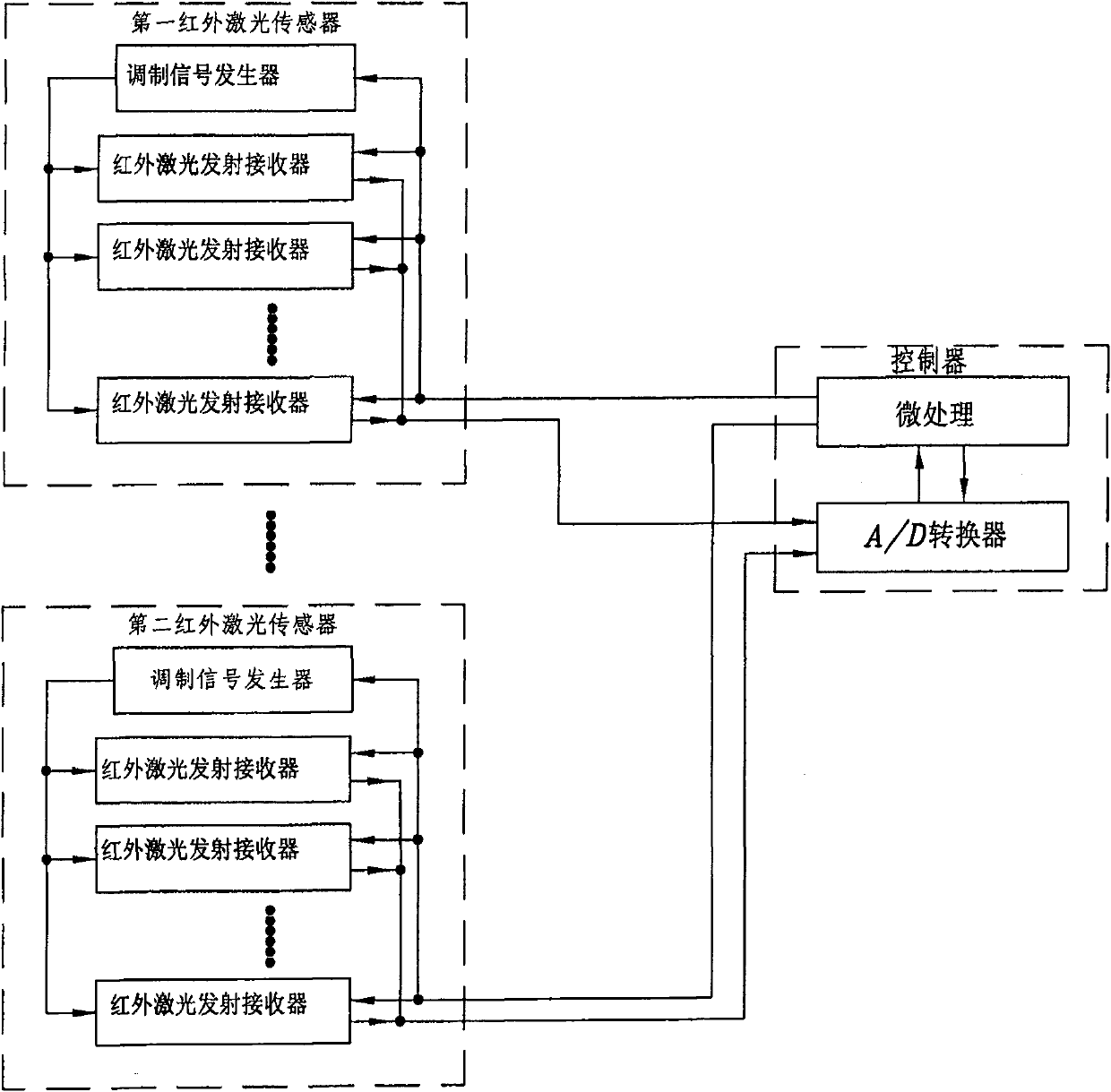
[0026] The first and second infrared laser sensors 1 and 2 respectively include two or more infrared laser transmitter receivers controlled by the controller to transmit and receive light beams in a ...

Embodiment 2

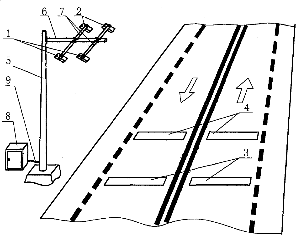
[0032] Example 2 (see image 3 ):

[0033] image 3 In order to be applied to the case of two-way two-vehicle lanes, the difference between Embodiment 2 and Embodiment 1 is that a pair of first and second infrared laser sensors 1 and 2 and their corresponding first and second infrared laser sensors located on the other lane are added. , the second reflective tape 3,4.

Embodiment 3

[0034] Example 3 (see Figure 4 ):

[0035] Figure 4 In order to apply to the case of two-way four-vehicle lanes without an isolation belt in the middle, the difference between implementation 3 and implementation 2 is that a bracket and two pairs of first and second infrared laser sensors located on the bracket are added, and the installation method is double-sided installation. Mode.


PUM


Abstract

The invention relates to an infrared laser traffic information collector which comprises a support positioned beside a road, a first infrared laser sensor, a second infrared laser sensor, a controller, a first reflective tape and a second reflective tape; wherein the first infrared laser sensor and the second infrared laser sensor are fixed on a cross bar positioned on the support, and are connected with the controller through cables; The infrared laser traffic information collector has the advantages that the installation is simple, and no portal frame is required to be arranged on the road;the overall cost is low; the influence on the aesthetic measure of the environment is greatly reduced; the collector can be suitable for being distributed in a high density detection station; and thescanning is performed through the light beam of the infrared laser sensors along the width of the traffic lane, so that miss of vehicle detection can not happen.

Description

technical field [0001] The invention relates to an infrared laser traffic information collector, which is suitable for an intelligent traffic system (ITS). It belongs to the technical field of laser technology application. Background technique [0002] With the rapid increase of traffic demand driven by the development of social economy, the dense road network cannot meet the needs of traffic growth. In addition to expanding the scale of the road network to solve the growing traffic demand, the use of advanced electronics, communications, computers and other high-tech to develop my country's intelligent transportation system (ITS), strengthen the management of existing road transportation, improve the road network capacity and the quality of transport services are very important. [0003] The technologically advanced and practical traffic information collection device is an important part of the Intelligent Transportation System (ITS). At present, the automatic collection e...

Claims


Application Information

Patent Timeline
Patent Type & Authority Patents(China)
IPC IPC(8): G08G1/04
Inventor 李令义石林波
Owner ZHONGJIAO YUANZHOU TRAFFIC TECH GROUP
Why Eureka
Try Eureka