
Gas fuel system for motor vehicle

A gas fuel, motor vehicle technology, applied to vehicle components, layout in combination with internal combustion engine fuel supply, gas/liquid distribution and storage, etc., to achieve the effect of less hardware changes

Inactive Publication Date: 2010-02-17
FORD GLOBAL TECH LLC
View PDF8 Cites 0 Cited by
  • Summary
  • Abstract
  • Description
  • Claims
  • Application Information

AI Technical Summary

Problems solved by technology

A pressure sensor generates a gas pressure signal corresponding to the tank pressure

Method used


Image

  • Gas fuel system for motor vehicle
  • Gas fuel system for motor vehicle
  • Gas fuel system for motor vehicle

Examples


Embodiment Construction

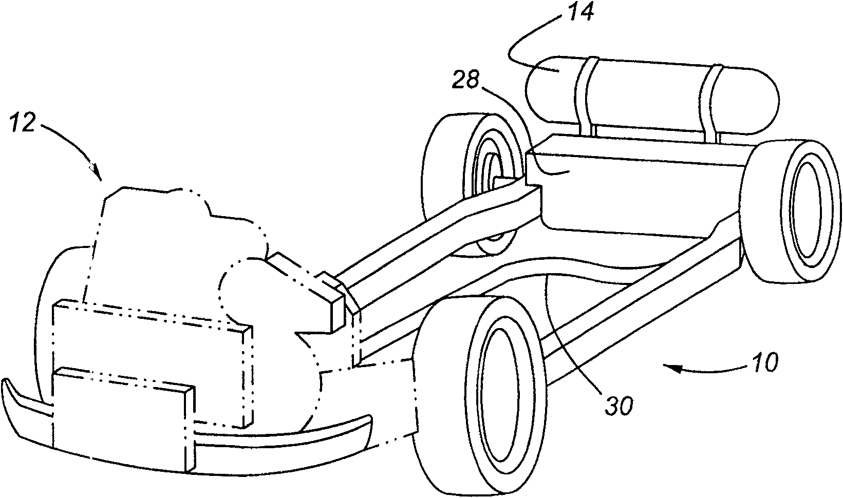
[0023] like figure 1 As shown, the vehicle 10 includes a compressed fuel storage tank 14 that can hold natural gas, hydrogen, or some other compressed fuel gas. Fuel is provided to prime mover 12 via fuel transfer line 30 . As noted above, prime mover 12 may comprise a fuel cell or an internal combustion engine, or other type of compressed gaseous fuel known to those skilled in the art or suggested for use with a prime mover by the present invention.

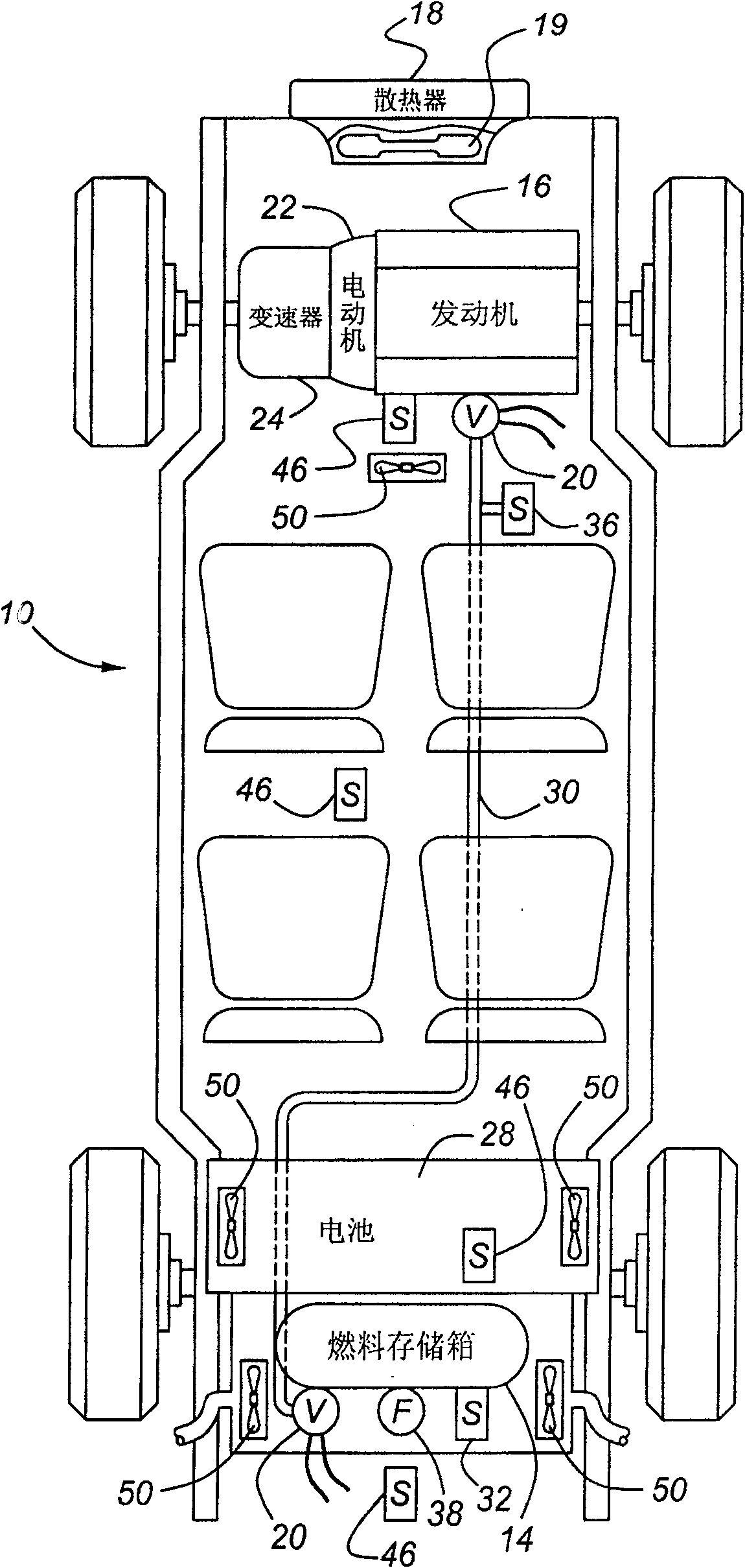
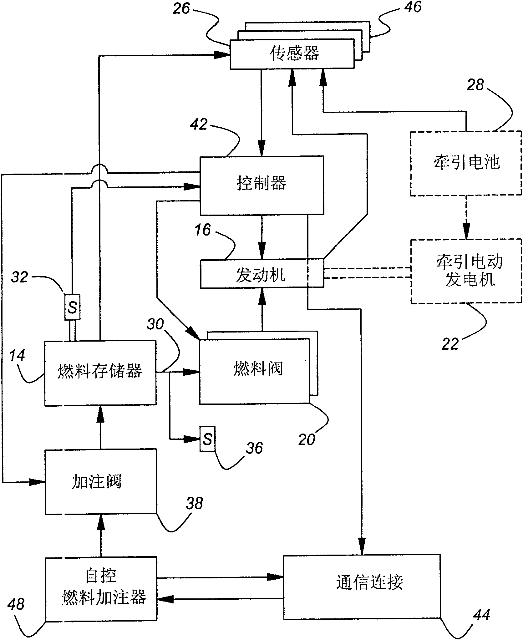
[0024] figure 2 Additional details of the vehicle and fuel system of the present invention are shown. A first type of prime mover comprises an engine 16 , cooled by a radiator 18 and a circulating fan 19 , connected to a traction motor 22 and a transmission 24 . Engine 16 receives fuel from storage tank 14 via fuel transfer line 30 . The flow of fuel via fuel transfer line 30 is controlled by fuel valve 20 positioned between fuel transfer line 30 and fuel storage tank 14 and between fuel transfer line 30 and engine 16 . Al...


PUM


Abstract

A gas fuel system for motor vehicles includes a gas fuel storage box and a correlative pressure transducer for monitoring the pressurization gas in the storage box. A parameter driver is used for monitoring the completeness of the storage box by tracking filling circulation of the pressure in the storage box. If the filling circulation is over the preset times or the other system completeness monitoring indication needs to be regulated, the regulating action can be adopted.

Description

technical field [0001] This invention relates to gaseous fuel storage and delivery systems for use in motor vehicles. Background technique [0002] Gaseous fuel storage and supply systems for motor vehicles present unique challenges to motor vehicle designers because such fuel systems need to be handled at relatively high pressures compared to the moderate pressures associated with handling liquid fuels such as gasoline and diesel gas. Additionally, certain compressed gases, such as hydrogen and natural gas, present additional challenges because such gases are buoyant in comparison, whereas vapors typically produced from liquid hydrocarbon fuels lack buoyancy. In addition, hydrogen is not only buoyant, but also odorless and has a smaller molecular size than the vapors produced by liquid hydrocarbon fuels. All of these characteristics make compressed fuel gas more difficult to store. [0003] The need to store compressed gas at relatively high pressures and motor vehicle s...

Claims


Application Information

Patent Timeline
Patent Type & Authority Patents(China)
IPC IPC(8): F17C5/00F17C13/00B60K15/00B60K5/00B60K1/00
Inventor 迈克尔·J·维斯特那梅吉德·穆罕默德丹尼尔·J·威勒斯基布莱恩·C·摩尔赫德
Owner FORD GLOBAL TECH LLC
Learn More