
A monitoring method and system for a secondary circuit

A secondary circuit and circuit technology, applied in the field of power systems, can solve problems such as time-consuming and labor-intensive, secondary circuit grounding short circuit, inconsistent number or position, etc.

Active Publication Date: 2021-02-02
YUNNAN POWER GRID CO LTD ELECTRIC POWER RES INST
View PDF11 Cites 0 Cited by
  • Summary
  • Abstract
  • Description
  • Claims
  • Application Information

AI Technical Summary

Problems solved by technology

[0003] The wide variety of secondary equipment leads to complicated secondary wiring. There are hundreds of terminal block wiring in a protection control panel cabinet. The secondary circuit is prone to failure. The basic fault types of the secondary circuit do not match the reality. That is, the actual wiring does not match the drawing number or position due to reasons such as not considering the specific installation conditions or equipment signals during the design; the secondary circuit is disconnected; the secondary circuit is grounded and short-circuited, and the secondary circuit is mixed.
[0004] Once some secondary circuits fail, it is very difficult for the staff to find out the faults in a short time, and the secondary wiring forms are ever-changing and the wiring is dense. It will take time and effort to check one by one. Therefore, a fast and accurate Secondary circuit monitoring method and system

Method used


Image

  • A monitoring method and system for a secondary circuit
  • A monitoring method and system for a secondary circuit
  • A monitoring method and system for a secondary circuit

Examples


Embodiment 1

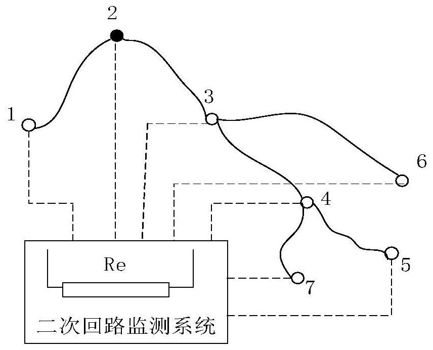
[0098] In the embodiment of the present invention, specific reference image 3 and Figure 4 , image 3 It is one of the application schematic diagrams of a monitoring method for a secondary circuit provided in Embodiment 1 of the present invention; Figure 4 It is one of the application schematic diagrams of a monitoring method for a secondary circuit provided by Embodiment 1 of the present invention. Such as image 3 Take 2 nodes as the signal source point, 1, 3, 4, 5, 6, 7 as the test points, connect the positive potential at the 2 nodes, and respectively form a circuit through the protection resistor and the test point in the following way: 21, 23, 24 , 25, 26, 27, the current signal direction should be 2→1, 2→3, 2→3→4, 2→3→4→5, 2→3→6, 2→3→4→7. If the current direction and the node signal do not match this, it is judged that the graph does not match. The resistance of each circuit is Resistance to ground (mn takes 21, 23, 24, 25, 26, 27).


PUM


Abstract

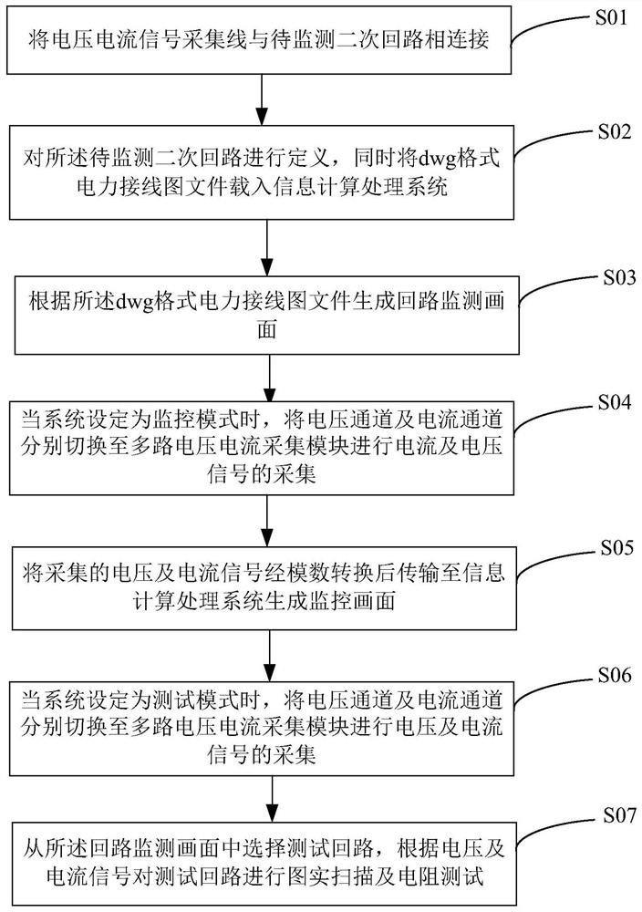
The application provides a monitoring method and system for a secondary circuit, wherein the monitoring method includes loading the dwg format power wiring diagram file into the information calculation and processing system; generating a circuit monitoring screen according to the dwg format power wiring diagram file; when the system is set When the monitoring mode is set, the monitoring screen is generated according to the collected voltage and current signals; the monitoring screen is convenient for the staff to monitor the operating conditions of the secondary circuit at any time; when the system is set to the test mode, the test circuit is tested according to the voltage and current signals Real-time scanning and resistance test, wherein real-time scanning can detect whether the actual connection of the secondary circuit is consistent with the drawing information, and the resistance test can check whether each secondary circuit is faulty according to the size of the resistance. Therefore, a kind of The monitoring method for the secondary circuit can not only record the working conditions of the secondary circuit when it is working normally, but also can be used for detection when the secondary circuit fails.

Description

technical field [0001] The present application relates to the technical field of power systems, and in particular to a monitoring method and system for a secondary circuit. Background technique [0002] Secondary equipment is suitable for low-voltage electrical equipment that detects, controls, measures, regulates and protects the working conditions of power systems and primary equipment, including measuring instruments, primary equipment control, operation monitoring signals, automatic monitoring systems, and relay protection And safety automatic devices, communication equipment, etc., the electrical circuit formed by connecting the secondary equipment according to certain functional requirements is collectively called the secondary circuit. The secondary circuit is indispensable to ensure the safe production, economical operation and reliable power supply of the power system. An important part of. [0003] The wide variety of secondary equipment leads to complicated secon...

Claims


Application Information

Patent Timeline
Patent Type & Authority Patents(China)
IPC IPC(8): G01R31/50G01R31/08
CPCG01R31/08G01R31/50
Inventor 彭俊臻张丽陈勇韩钰何廷一和鹏
Owner YUNNAN POWER GRID CO LTD ELECTRIC POWER RES INST
Learn More