
Device for introducing adhesive into a heatable pasting device

A technology of adhesive and accommodating device, which is applied to the device, packaging, labeling machine and other directions for coating liquid on the surface, can solve the problem of not ensuring the placement of the adhesive transport container and so on.

Inactive Publication Date: 2010-03-03
KRONES AG
View PDF7 Cites 0 Cited by
  • Summary
  • Abstract
  • Description
  • Claims
  • Application Information

AI Technical Summary

Problems solved by technology

[0005] However, these solutions have the disadvantage that an optimal placement of the adhesive delivery container on the holding device or on the container to be installed, in particular the storage container of the glue application unit, cannot be guaranteed.

Method used


Image

  • Device for introducing adhesive into a heatable pasting device
  • Device for introducing adhesive into a heatable pasting device
  • Device for introducing adhesive into a heatable pasting device

Examples


Embodiment Construction

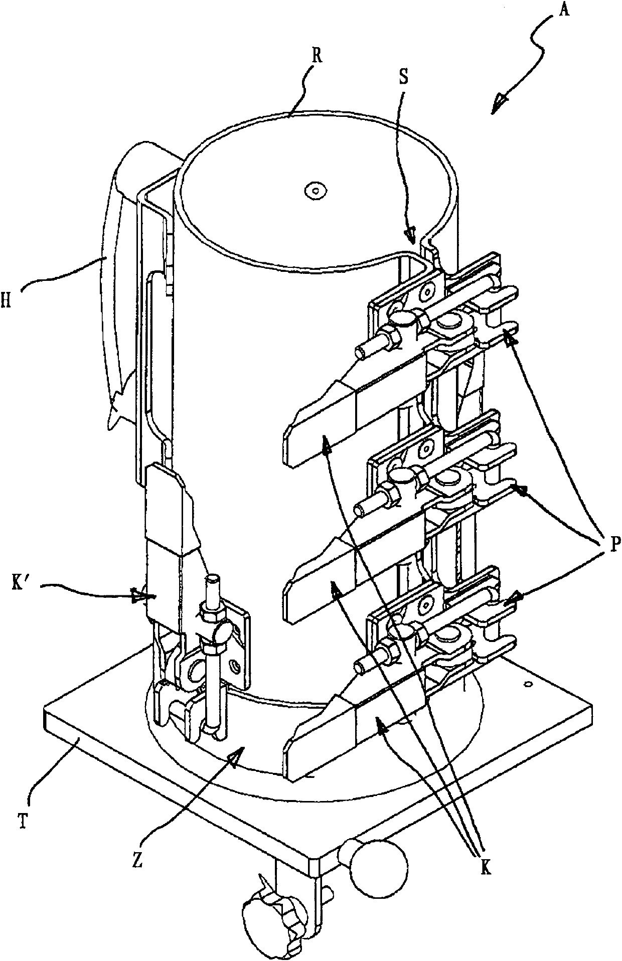
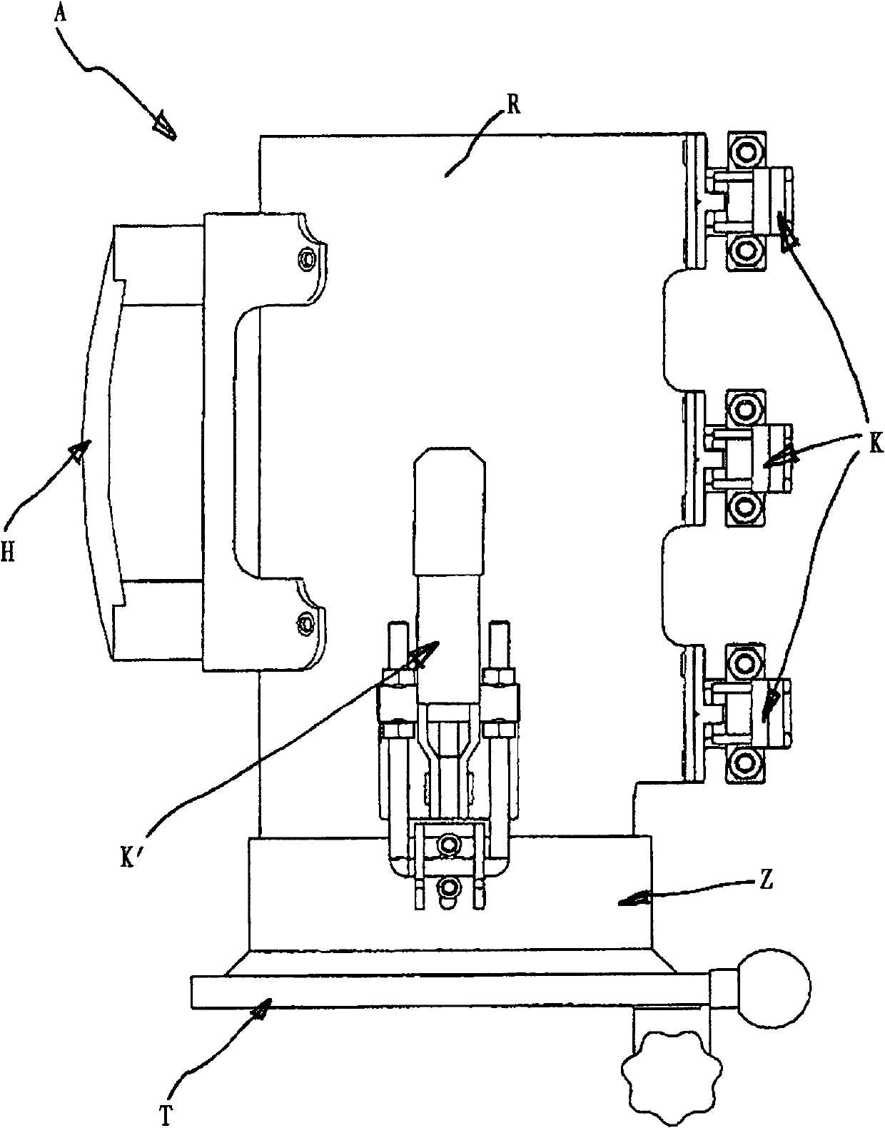
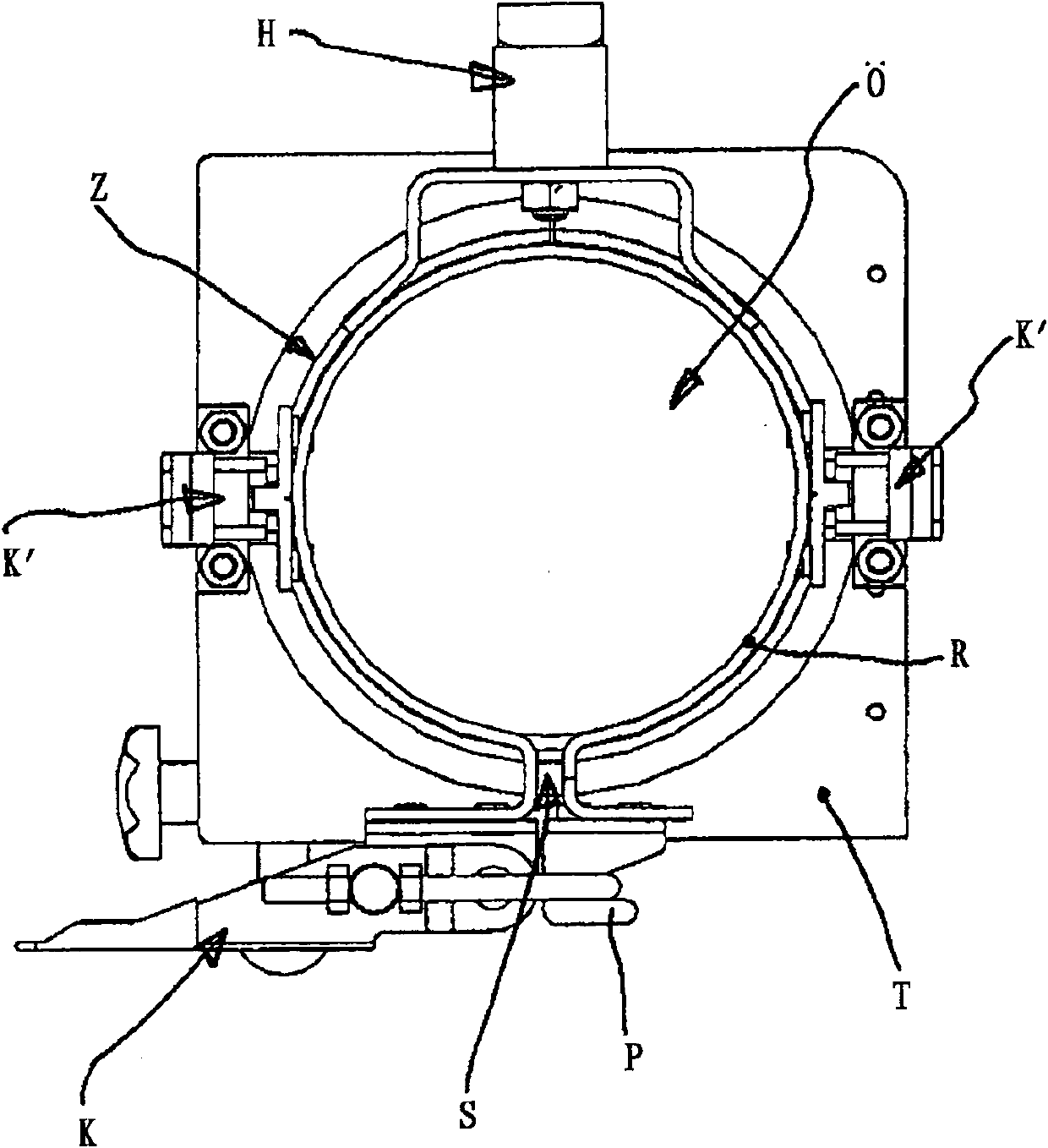
[0016] according to figure 1 The receiving device A basically consists of a tubular body R with a laterally mounted handle H and a support plate T with a centering ring Z. Centering ring Z consists of a image 3 The circular opening in the support plate T shown in

[0017] The support plate T is arranged in a labeling machine for bottles or jars etc., in the Figure 4 Above the filling opening of the storage container V of the gluing mechanism L shown in , for example around a swivel hinge mounted on the upper side. The gluing unit L can be heated by means of an electric heating element E in the storage container V in a manner known per se.

[0018] The tubular body R consists of a circularly curved plate and has a slot S extending continuously over its entire length. The two edges of the plate pointing towards each other at the slot S are each bent outwards in an approximately U-shape and form receiving arms for the toggle quick release K and its clamping hook P.

[00...


PUM


Abstract

The invention relates to a device for introducing an adhesive into a heatable pasting device (L), comprising a container (V), by means of a heatable receiving device for an adhesive transport container.

Description

technical field [0001] The invention relates to a device for introducing an adhesive which is not flowable at room temperature into a heatable gluing unit. Background technique [0002] The gluing unit of a labeling machine or other packaging machine usually has a storage container with an integrated heating device for the adhesive in order to heat the adhesive to the required processing temperature at which the adhesive is then In the liquid phase (see Figures 14-17 of DE 2941458 or DE 9102068U). This can be, for example, a UV-curable thermal glue (eg KRONES-colfix HM 3002) which has a waxy consistency at room temperature and which is provided by the manufacturer filled in a transport container such as a metal can or the like. The processing temperature in the gluing mechanism is in the range between 100°C and 120°C. It is problematic to put the hard adhesive into the storage container of the gluing unit. Hitherto the adhesive had to be softened in a hot water bath or re...

Claims


Application Information

Patent Timeline
Patent Type & Authority Patents(China)
IPC IPC(8): B65C9/22B05C11/10B29B13/02B65C9/20
CPCB65C9/22B29K2105/0097B05C11/1042B29B13/022
Inventor R·塔勒尔
Owner KRONES AG
Learn More