
Carbon fiber yarn breaking device

A carbon fiber yarn and yarn breaking technology, which is applied in textiles, papermaking, knitting, etc., can solve the problems of reducing production efficiency, impact, and movement of carbon fiber yarn surface, and achieve the effects of prolonging service life, reducing use cost, and avoiding collisions

Active Publication Date: 2013-11-20
CHANGZHOU HONGFA ZONGHENG ADVANCED MATERIAL TECH
View PDF6 Cites 0 Cited by
  • Summary
  • Abstract
  • Description
  • Claims
  • Application Information

AI Technical Summary

Problems solved by technology

[0002] In the weaving process of carbon fiber yarn, it is necessary to cut the carbon fiber yarn surface. The existing cutting method is the principle of cylinder push, and the carbon fiber yarn surface is cut flat. After a long time, the knife edge will form an uneven knife-edge cutting yarn surface, so that the yarn surface will not be cut at one time and affect the production of the entire equipment during cutting. The result is that either the yarn surface cannot be cut, or the blade It will be broken and scrapped, which affects the continuation of production, reduces production efficiency, and increases the cost of equipment use
At the same time, in the carbon fiber cutting process, the carbon fiber yarn surface needs to be compacted. The existing compaction method is not firm. The quality of noodles affects production efficiency
[0003] The carbon fiber yarn surface is pulled out by the clamping device of the weft laying device. Under different working conditions, the upper clamping block and the lower clamping block in the yarn clamping device will move up and down, so that the upper clamping block, the lower clamping The carbon fiber yarn surface clamped by the yarn block will also move up and down accordingly, and the up and down movement of the carbon fiber yarn surface, without the support device below the yarn surface, will lead to the phenomenon of yarn disorder, and the yarn disorder will affect the work efficiency. It is also easy to cause the quality of the woven products to fail to meet the requirements

Method used


Image

  • Carbon fiber yarn breaking device
  • Carbon fiber yarn breaking device
  • Carbon fiber yarn breaking device

Examples


Embodiment Construction

[0037] The present invention will be further described below in conjunction with the accompanying drawings and specific embodiments.

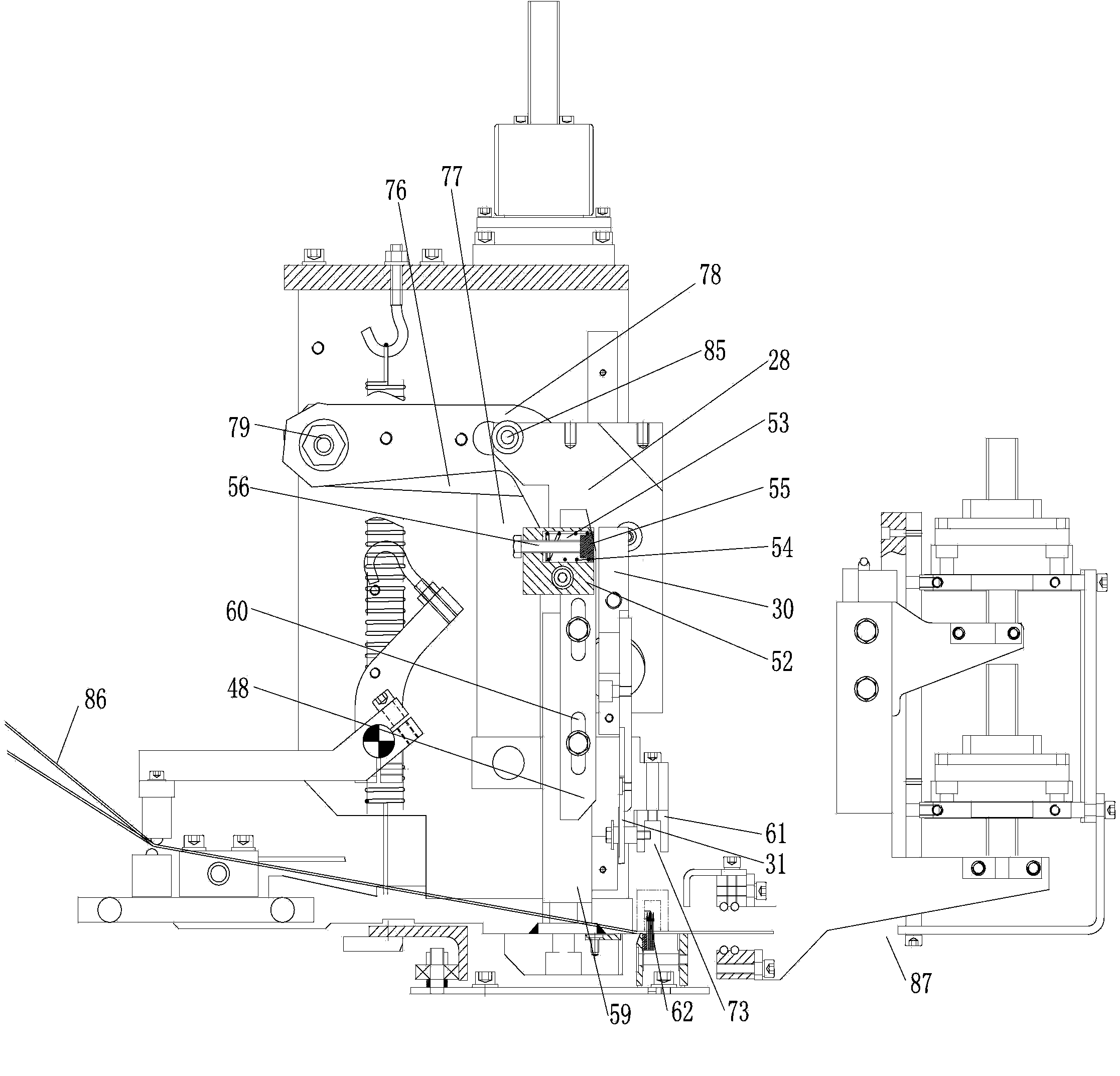
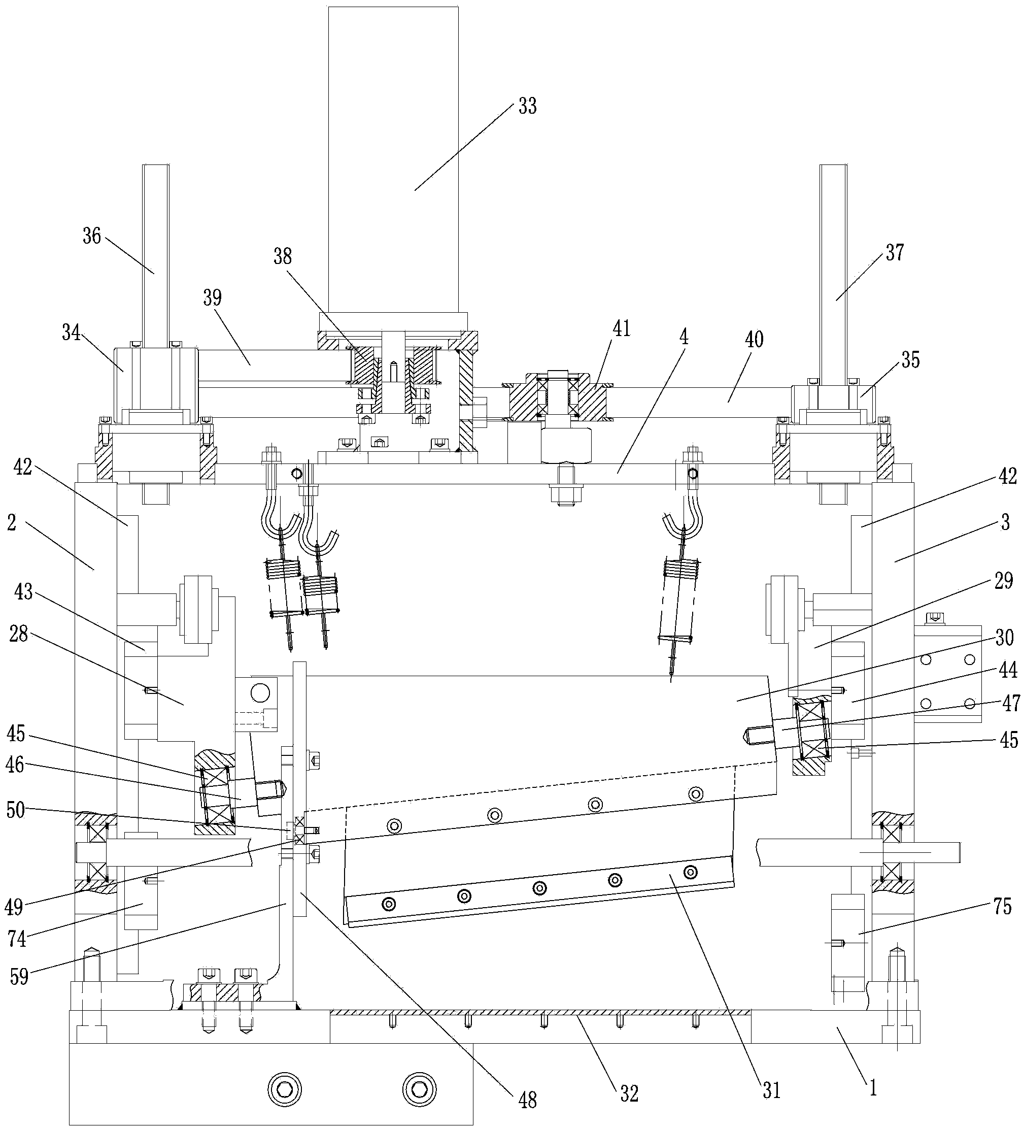
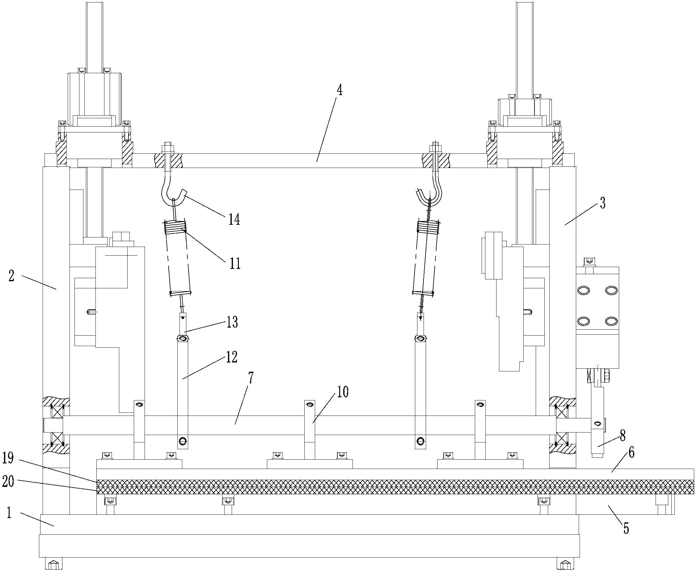
[0038] see Figure 1-11 , the carbon fiber yarn breaking device, comprising a base 1, a left mounting plate 2 and a right mounting plate 3 vertically arranged on the base, an upper mounting plate 4 is fixedly arranged between the left mounting plate and the right mounting plate, and the front portion of the base is arranged There is a yarn clamping mechanism for clamping the yarn, a yarn lifting mechanism for lifting the yarn in the middle, a yarn breaking mechanism for cutting the yarn at the rear, and a yarn cutting mechanism on the side of the yarn breaking mechanism. Yarn pressing mechanism for pressing;

[0039] see image 3 , 4 , 9. The yarn clamping mechanism includes the lower pressing plate 5 on the base 1, the upper pressing plate 6 that cooperates with the lower pressing plate 5, and the driving upper pressing plate 6 that is arra...


PUM


Abstract

The invention relates to a carbon fiber breaking device which comprises a base, a left mounting plate and a right mounting plate, wherein the left mounting plate and the right mounting plate are vertically arranged on the base; an upper mounting plate is fixedly arranged between the left mounting plate and the right mounting plate; a yarn clamping mechanism for clamping yarns is arranged at the front part of the base; a yarn lifting mechanism for lifting the yarns is arranged at the middle of the base; and a yarn breaking mechanism for cutting off the yarns and a yarn pressing mechanism which is positioned on one side of the yarn breaking mechanism and is used for pressing the yarns are arranged at the rear part of the base. According to the carbon fiber breaking device disclosed by the invention, carbon fiber yarn surfaces which move vertically can be supported in real time so as to the avoid the phenomenon of yarn mess; in the cutting process, the carbon fiber yarn surfaces can be obliquely cut from one point of the carbon fiber yarn surfaces, so that the phenomena that the yarn surfaces cannot be cut off and a blade is broken and scraped are avoided; and meanwhile, in the cutting process, the carbon fiber yarn surfaces can be firmly pressed, so that the precision of broken yarns and the quality of carbon fiber yarn surfaces are ensured, the production efficiency is increased and the use cost of the equipment is also reduced.

Description

technical field [0001] The invention belongs to the technical field of textile machinery, and in particular relates to a carbon fiber yarn breaking device. Background technique [0002] In the weaving process of carbon fiber yarn, it is necessary to cut the carbon fiber yarn surface. The existing cutting method is the principle of cylinder push, and the carbon fiber yarn surface is cut flat. After a long time, the knife edge will form an uneven knife-edge cutting yarn surface, so that the yarn surface will not be cut at one time and affect the production of the entire equipment during cutting. The result is that either the yarn surface cannot be cut, or the blade It will be broken and scrapped, which affects the continuation of production, reduces production efficiency, and increases the cost of equipment use. At the same time, in the carbon fiber cutting process, the carbon fiber yarn surface needs to be compacted. The existing compaction method is not firm. The quality o...

Claims


Application Information

Patent Timeline
Patent Type & Authority Patents(China)
IPC IPC(8): D04B35/00
Inventor 谈昆伦陈震陈龙谈良春
Owner CHANGZHOU HONGFA ZONGHENG ADVANCED MATERIAL TECH
Learn More