Method for integrating a light guide in or onto a support structure

A support structure and light guide technology, applied in the coupling of optical waveguides, light guides, optics, etc., can solve problems such as deterioration of light guide performance

Inactive Publication Date: 2010-03-17
KONINKLIJKE PHILIPS ELECTRONICS NV
View PDF2 Cites 0 Cited by
  • Summary
  • Abstract
  • Description
  • Claims
  • Application Information

AI Technical Summary

Problems solved by technology

[0003] However, when such a lightguide is integrated into or onto a support structure, its light-guiding performance is degrade

Method used


Image

  • Method for integrating a light guide in or onto a support structure
  • Method for integrating a light guide in or onto a support structure
  • Method for integrating a light guide in or onto a support structure

Examples


Embodiment Construction

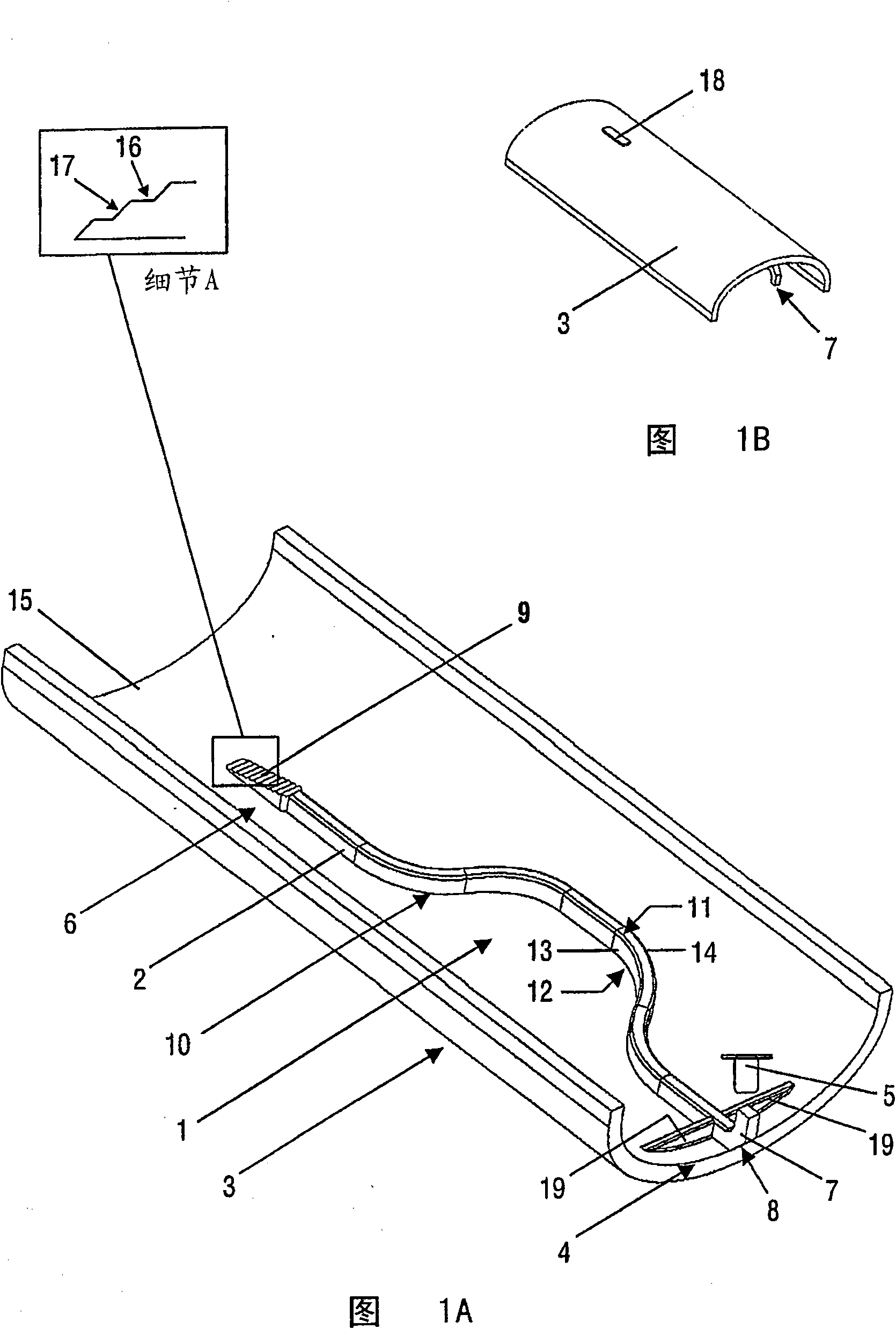
[0028] In the specification, the term "light guide" means to include all transparent structures arranged to guide light from a first position to a second position along a predetermined length. Generally, such light guides have a length greater than the dimension of their cross-section. However, in this specification, structures with a small length, such as windows, are also included in the meaning of the term "light guide".

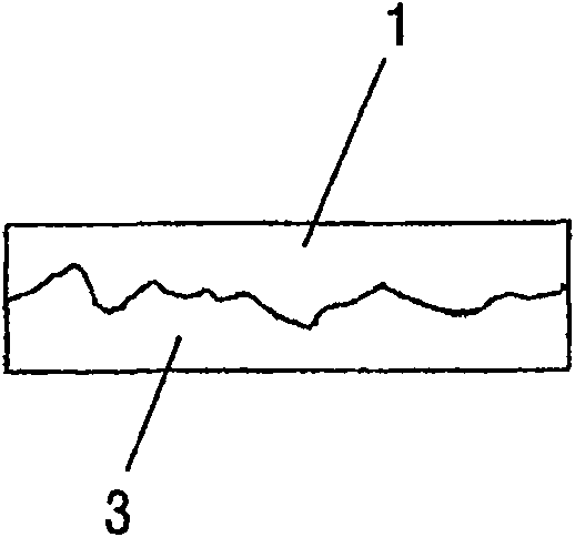
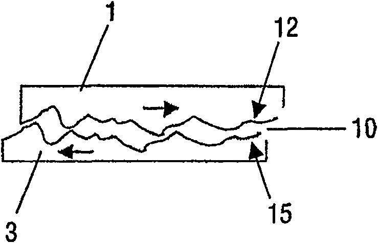
[0029] FIG. 1 shows the light guide 1 extending along the inner side 15 of the support structure 3. The parts 1, 3 are all molded from plastic and separated from each other by a small gap 10 extending between their respective abutting surfaces 12, 15, which is better shown in FIG. 2.

[0030] In the illustrated embodiment, the supporting structure 3 is of a partially cylindrical design, for example, it may form a part of a device or constitute a housing or internal structure of the device, especially an electronic device. Of course, the structure 3 can have ...


PUM


Abstract

The invention relates to a method for integrating a light guide (1) in or onto a support structure (3), wherein said parts (1,3) are molded and wherein during this molding and/or a subsequent coolingdown process, shrink behavior of the respective parts (1,3) is controlled in such way that both parts (1,3) shrink incompatibly, at least temporarily and at least near their bordering areas, thereby causing the parts (1,3) to be separated and an air gap (10) to be formed between their respective separation surfaces. Separation of the parts (1,3) can be promoted by making the parts of materials having incompatible melting points and/or incompatible chemical bonding properties. Incompatible shrinkage can be stimulated by appropriate parts design, by applying materials having incompatible shrinkbehavior and/or by exposing the parts to different molding and cooling down conditions. The invention furthermore relates to a support structure with light guide and a device comprising such a supportstructure.

Description

Technical field [0001] The present invention relates to a method for integrating a light guide into or on a supporting structure, such as a housing, frame or carrier plate of an electronic device. Background technique [0002] Many devices use light guides. These light guides have a rod or rod-like structure, which is made of transparent materials and is arranged to guide light between the light generating source (located in the first position) and the device that requires light supply (located in the second position), such as a photosensitive element Or a light indicator, which reminds the user to pay attention to the special status of the device, such as operating mode, alarm status, charging status, or error occurrence status. Due to such a light guide, the light generating source can be arranged at a convenient location that is removed from the place where light is required, thereby increasing the degree of freedom of design. [0003] However, when such a light guide is integ...

Claims


Application Information

Patent Timeline
IPC IPC(8): B29D11/00B29C45/14
CPCB29D11/00701B29K2995/0049B29L2011/0075B29C45/16B29C2045/1601G02B6/24G02B6/255
Inventor W·S·威杰马L·J·布罗沃
Owner KONINKLIJKE PHILIPS ELECTRONICS NV
Why Eureka
Try Eureka