
Method and apparatus for controlling video encoding data rate

Inactive Publication Date: 2008-01-31
SAMSUNG ELECTRONICS CO LTD
View PDF7 Cites 15 Cited by
  • Summary
  • Abstract
  • Description
  • Claims
  • Application Information

AI Technical Summary

Benefits of technology

[0013]Accordingly, the present invention has been made to solve in part at least some of the above-mentioned problems occurring in the prior art. Moreover, the present invention provides a method for controlling a video encoding data rate in real time in order to minimize performance deterioration, even when a scene change has occurred in an application field having a small number of available bits due to a low bit rate and a high frame rate.

Problems solved by technology

Recent advances in areas such as High Definition broadcasts only increases the demand for transfer of high quality images over available bandwidth.
However, a communication network by which the video data is transferred may limit the data rate applied to the encoding to a constant value.
Therefore, a video encoding process normally compromises some of its capability in that typically there is an alternative trade off regarding the number of bits required to attain the desired image quality and the image compression.
Also, video encoding requires a number of relatively complex processes and lots of CPU cycles comparatively in operation by using software.
Furthermore, there is a problem when video encoding is processed and reproduced in real time, as the time condition limits the accuracy in operation of the encoding, and thereby the quality of the video is restricted.
If scene change occurs in an interframe, video quality cannot be prevented from deteriorating before using many more bits than those estimated by encoding data rate control.
That is, if scene change is not considered in encoding data rate control, serious performance deterioration may occur.
However, in an application field having a small number of available bits per frame due to a low bit rate and a high frame rate, significant problems may occur when the video encoding data rate control is performed by the afore-described scheme.
In other words, in such an application field, if many bits are assigned to a corresponding frame when scene change has occurred, it is impossible to avoid performance deterioration in remaining frames.

Method used


Image

  • Method and apparatus for controlling video encoding data rate
  • Method and apparatus for controlling video encoding data rate
  • Method and apparatus for controlling video encoding data rate

Examples


Embodiment Construction

[0019]Exemplary embodiments of the present invention will be described in detail herein below with reference to the accompanying drawings. It is to be understood that the examples shown and described have been provided for purposes of illustration and not to limit the invention to the exemplary embodiments herein. Particular items, such as detailed elements, are shown, but these items are provided for aiding the general understanding of the present invention, and it will be understood by those skilled in the art that such particular items can be modified within the scope of the present invention.

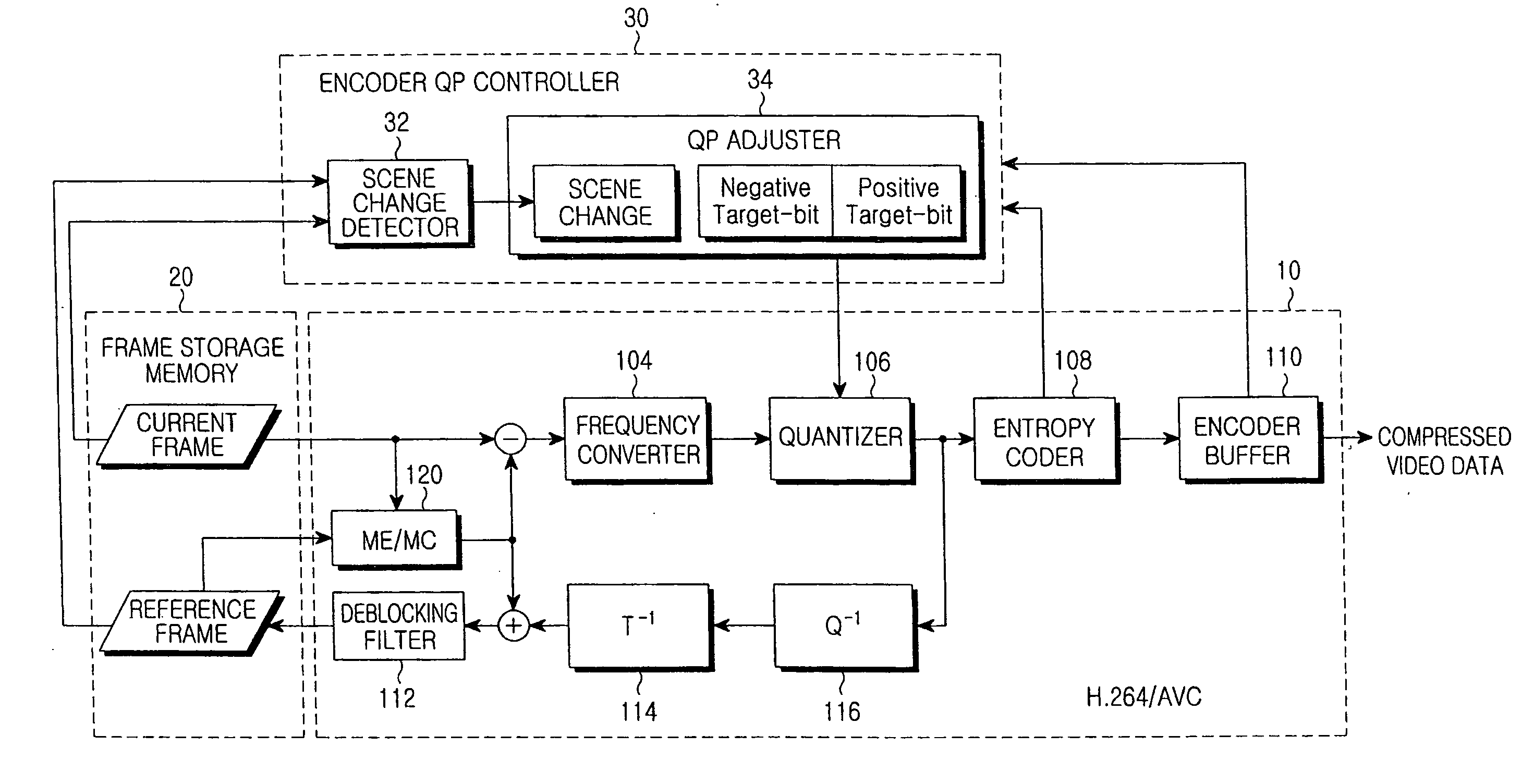
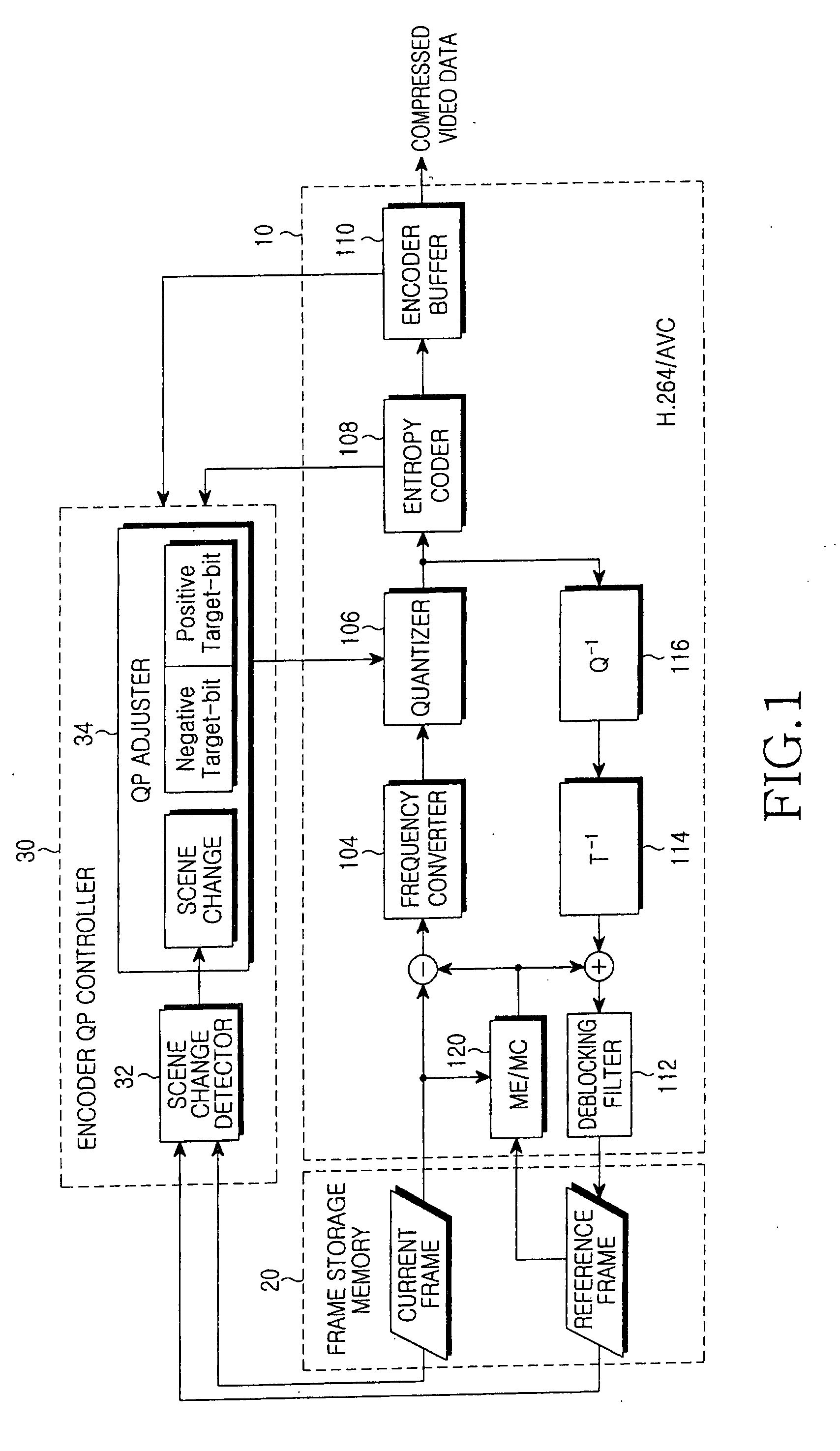
[0020]FIG. 1 is a block diagram of a video encoder device according to the present invention. Referring to FIG. 1, the video encoder device can include a general H.264 / AVC encoder 10 for receiving video frame sequences and outputting compressed video data. Further, the video encoder device includes a frame storage memory 20 for storing frames, and an encoder QP controller 30 for performing a...


PUM


Abstract

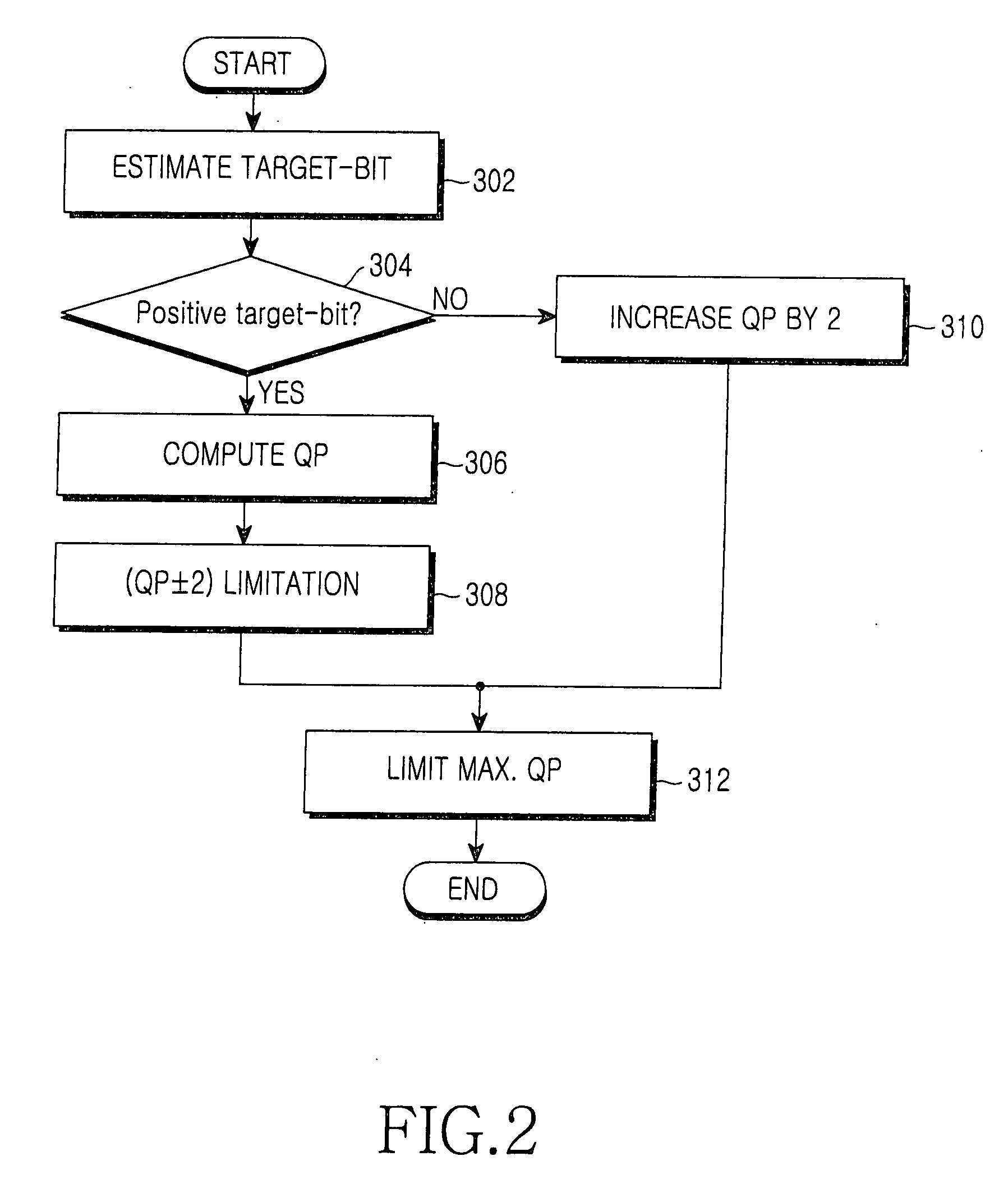
A method and apparatus for controlling a video encoding data rate in real-time in order to minimize performance deterioration, even when a scene change has occurred in an application field having a small number of available bits due to a low bit rate and a high frame rate. The method includes: a first step of determining whether scene change has occurred in a current frame; a second step of determining whether a number of current available bits is more than a preset reference when it is determined that the scene change has occurred; and a third step of adjusting a Quantization Parameter (QP) according to a first preset condition when it is determined that the number of current available bits is more than that preset reference. An apparatus includes an encoder QP controller having a QP module for adjusting the QP.

Description

CLAIM OF PRIORITY[0001]This application claims priority from an application entitled “Method For Controlling Video Encoding Data Rate,” filed in the Korean Intellectual Property Office on Jul. 27, 2006 and assigned Serial No. 2006-70856, the contents of which are hereby incorporated by reference in its entirety.BACKGROUND OF THE INVENTION[0002]1. Field of the Invention[0003]The present invention relates to video encoding in scene changes. More particularly, the present invention relates to a method for controlling a video encoding data rate having particular applicability in environments having both a low bit rate and a high frame rate.[0004]2. Description of the Related Art[0005]Various digital video compression technologies have been proposed in order to obtain a low data rate, or for a smaller storage region maintaining high image quality when a video signal is transmitted or stored. Such video compression technology is disclosed in a number of international standards, such as H....

Claims


Application Information

Patent Timeline
IPC IPC(8): H04N7/26
CPCH04N19/115H04N19/61H04N19/86H04N19/142H04N19/124H04N7/24
Inventor LEE, CHANG-HYUNKIM, JAE-SEOKLEE, SEONG-JOOOH, YUN-JEJOO, YOUNG-HUN
Owner SAMSUNG ELECTRONICS CO LTD
Learn More