Dynamically optimized ballast

Active Publication Date: 2017-07-18
LOPRESTI SPEED MERCHANTS
View PDF2 Cites 0 Cited by
  • Summary
  • Abstract
  • Description
  • Claims
  • Application Information

AI Technical Summary

Benefits of technology

The objective of this patent is to offer a ballast that can protect HID lamps and extend their lifespan, especially in pulsing conditions or repeated power-on and power-off. The ballast has a timer, a current-switching device, a timed step-up module, and a step-down module. It can adjust the brightness of the lamp to reduce power consumption and prevent deterioration. The ballast optimizes the use of the lamp without causing systemic damage or catastrophic failures.

Problems solved by technology

First, when the vehicles or lighting appliances are in use of HID lamps lighting, the foregoing ballast will provide the HID lamp a fixed maximum current resulting in the HID lamp achieving maximum brightness in an instant upon ignition. This standard way of igniting the arc in the HID lamp will result in a steady deterioration of HID lamp and reducing the service life of HID lamp. Moreover, unfortunately, an HID lamp is performing a flashing function common in aviation and automotive industries, the power source's repeated power-on and power-out (also known as “cold start”) will cause irreparable damage to the HID lamp and catastrophic failures. For example: during takeoff and landing, an aircraft commonly perform a pulsing action as a pre-caution to increase the visibility of the aircraft by other aircraft and land operations. This pulsing action on a foregoing HID System will have a high failure rate—for this reason, the foregoing ballast not only reduce the service efficiency of HID lamp, it will seriously affect the traffic safety.
For instance, when an aircraft is in a taxiing-state, the lighting requirement is only so that the environment is knowing of its existence; a sustained maximum brightness will only increase power consumption and deterioration of HID lamp.

Method used


Image

  • Dynamically optimized ballast
  • Dynamically optimized ballast
  • Dynamically optimized ballast

Examples


Embodiment Construction

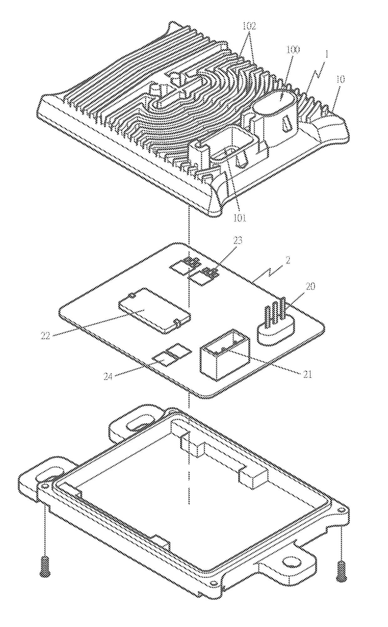
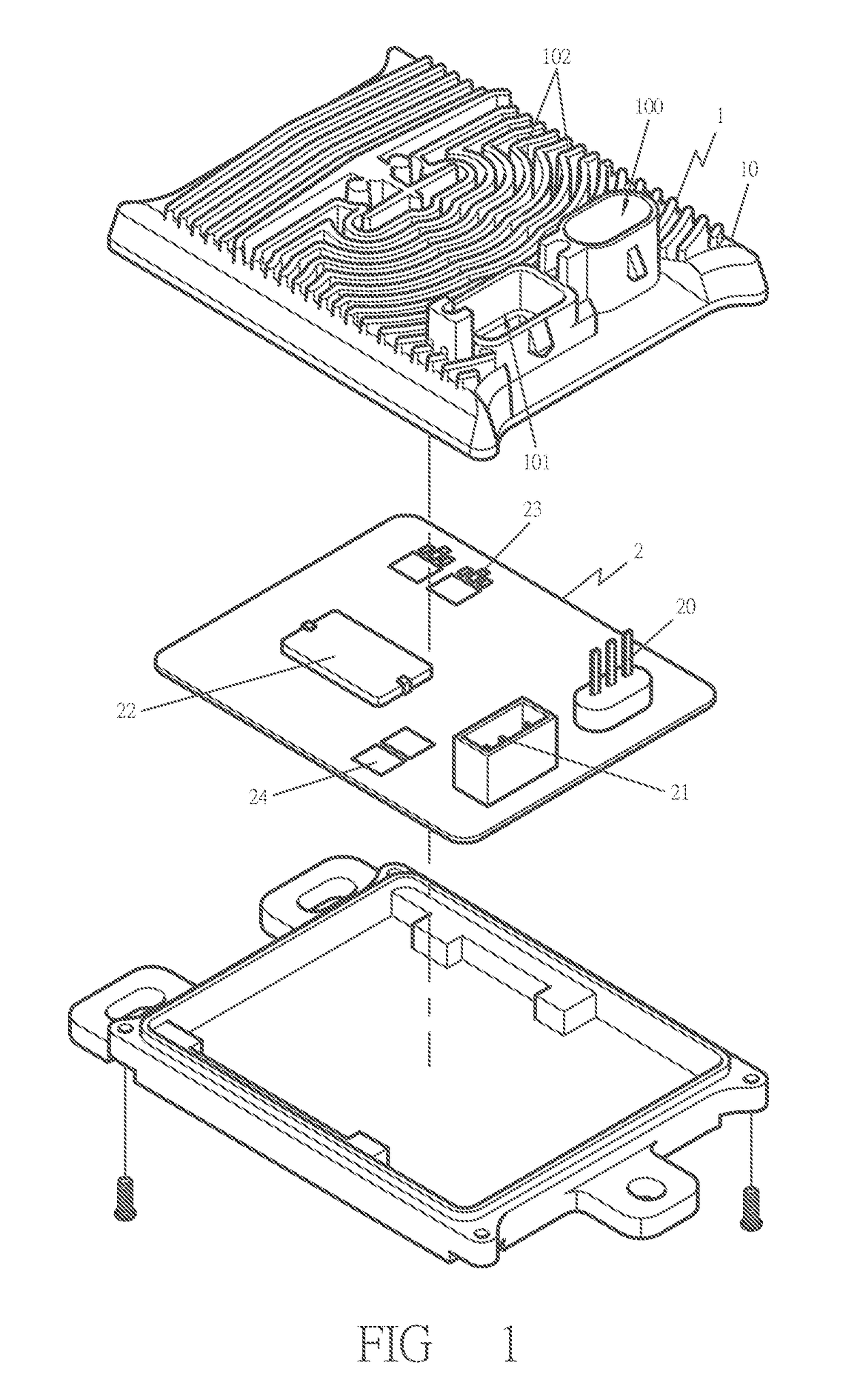
[0019]A preferred embodiment of a dynamically optimized ballast in the present invention, as shown in FIG. 1-5, includes a ballast 1 and a circuit board 2 as main components combined together.

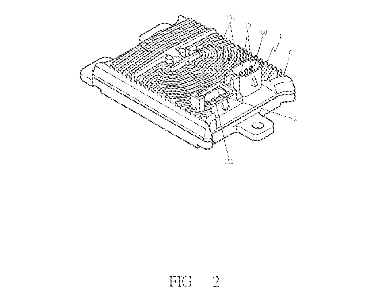
[0020]The ballast 1 has a case 10 provided with a power input base 100 and a power output base 101, an outer surface of said case 10 can be set with various modeling cooling member 102 to increase the cooling area and cooling effect of the case 10.

[0021]The circuit board 2 set inside said case 10 of the ballast, and provided with a power input socket 20, a power output socket 21, a microcontroller 22, a timer 23 and a current-switching device 24; wherein the power input socket 20 and power output socket 21 are set corresponding to said power input base 100 and power output base 101 of the case 10, and the microcontroller 22 is electrically connected to the power input socket 20, the power output socket 21, the timer 23 and the current-switching device 24.

[0022]As shown in FIG. 3, said microcont...


PUM


Abstract

A dynamically optimized ballast includes a ballast and a circuit board as main components combined together. Said circuit board is provided with a microcontroller, a timer and a current-switching device; wherein said microcontroller is provided with a timed step-up module which can start the timer and maintain a low current output to HID lamp at the time the circuit board is powered, and the timer will transmit a signal to the microcontroller to start the current-switching device and automatically switch to a high current output to HID lamp when a preset time of the timer has been reached. So that this invention can protect HID lamp and extend the service life of HID lamp, even the HID lamp pulsing for a long time, the power source repeated power supply and power out will not cause great damage to HID lamp and it will not be out of function. Besides, this invention enables user to reduce the brightness of HID lamp to reduce the loss of electric power and the deterioration of HID lamp.

Description

BACKGROUND OF THE INVENTION[0001]1. Field of the Invention[0002]This invention relates to dynamically optimized ballast, particularly to a ballast having a timer and a current-switching device to allow for multi-step output-levels, thereby eliminating the risk of systematic failures inherent with performing unregulated pulsing functions on HID (High Intensity Discharge) Systems.[0003]2. Description of the Prior Art[0004]At present, common HID lamps require use of ultra-high voltage to produce light from gas atoms excited by electric current. Typically, 12V or 24V DC (Direct Current) voltage is not enough to ignite the arc in the HID lamp, so a ballast is utilized between the HID lamp and Input Power to convert the DC voltage to AC (Alternating Current) voltage, and regulate the current supplied to the lamp throughout its operation.[0005]However, it will generate a lot of problems when using the foregoing ballast with HID lamps of the vehicles or lighting appliances, as described bel...

Claims


Application Information

Patent Timeline
IPC IPC(8): H05B37/02F21V29/74F21V23/06H05B41/38
CPCH05B41/38F21V23/06H05B37/0281F21V29/74H05B41/382Y02B20/00H05B47/16
Inventor LEANG, BOBBY
Owner LOPRESTI SPEED MERCHANTS
Why Eureka
Try Eureka