Light emitting device and light source module having thereof

a technology of light emitting devices and light sources, which is applied in the direction of basic electric elements, semiconductor devices, electrical appliances, etc., can solve problems such as deterioration of operation reliability, and achieve the effects of reducing transmission loss of uv-c wavelength, minimizing discoloration and deterioration

Active Publication Date: 2017-08-10
SUZHOU LEKIN SEMICON CO LTD
View PDF5 Cites 9 Cited by
  • Summary
  • Abstract
  • Description
  • Claims
  • Application Information

AI Technical Summary

Benefits of technology

[0017]The embodiment may be provided as a waterproof module within a product applied to high humidity and underwater environments.
[0018]The embodiment may be provided as a sterilizing device in a high humidity environment and underwater.
[0019]The embodiment may reduce transmission loss of a UV-C wavelength.
[0020]The embodiment may minimize discoloration and deterioration by UV-C.

Problems solved by technology

However, the environment in which the UV LED of a short wavelength is applied is mostly highly humid or inside water, so that dampproof and waterproof functions are deteriorated, and thus device failure is caused and operation reliability may be deteriorated.

Method used


Image

  • Light emitting device and light source module having thereof
  • Light emitting device and light source module having thereof
  • Light emitting device and light source module having thereof

Examples


first embodiment

[0045]Hereinafter, a light emitting device according to the present invention will be described with reference to FIGS. 1 to 6.

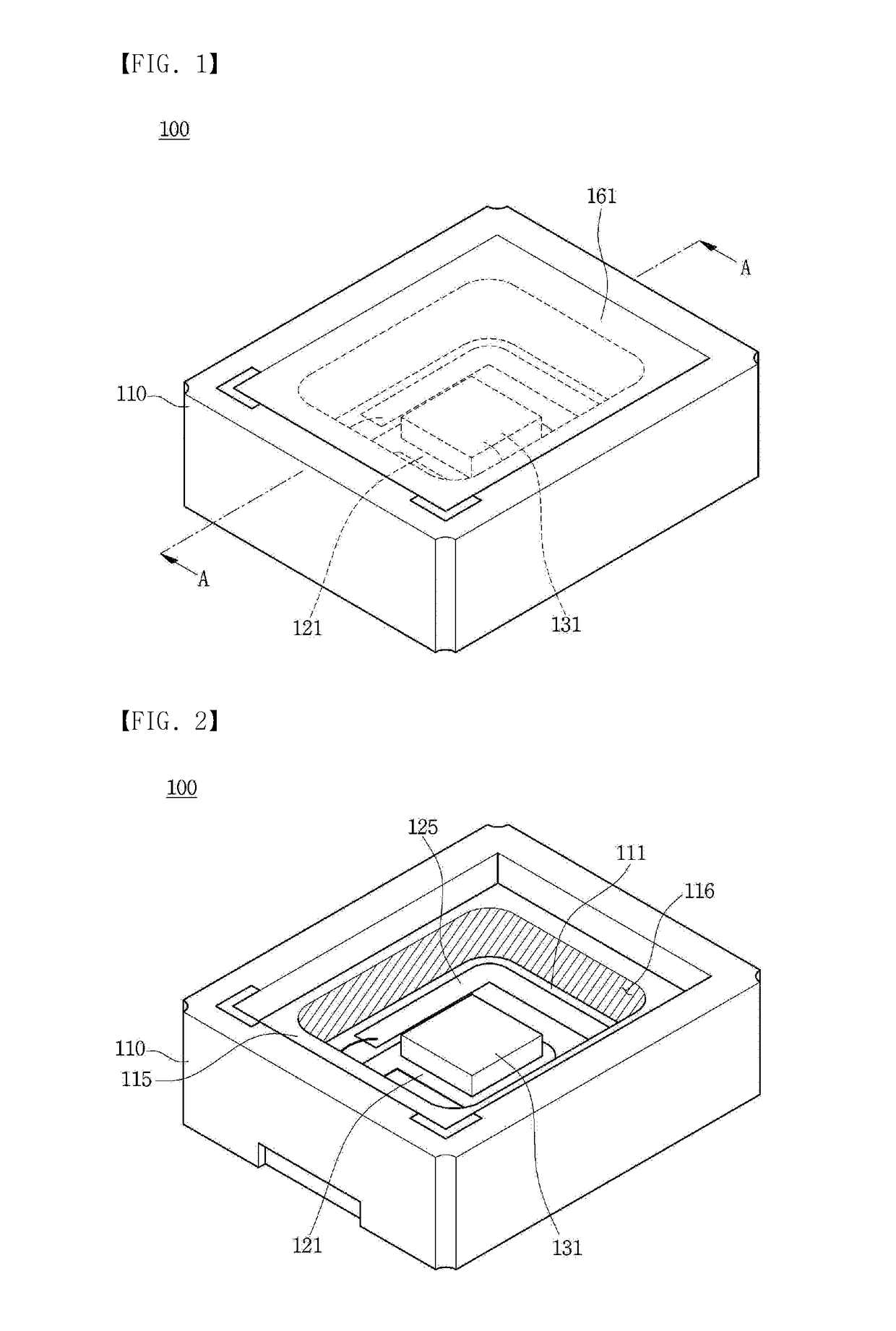
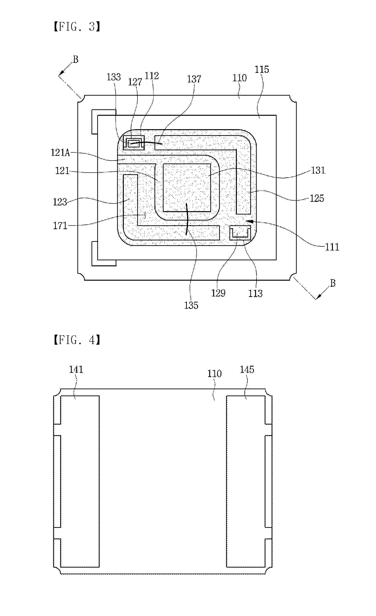
[0046]FIG. 1 is a perspective view of a light emitting device according to a first embodiment, FIG. 2 is a perspective view in which a light transmitting layer is removed in the FIG. 1, FIG. 3 is a floor plan view of the light emitting device of the FIG. 1 in which the light transmitting layer is removed, FIG. 4 is a rear view of the light emitting device of the FIG. 1, FIG. 5 is an A-A side cross-sectional view of the light emitting device of the FIG. 1 and FIG. 6 is a B-B side cross-sectional view of the light emitting device of the FIG. 3.

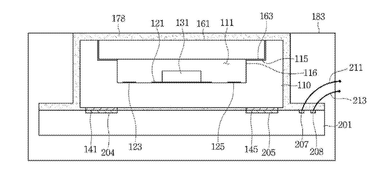
[0047]Referring to FIGS. 1 to 6, a light emitting device 100 includes a body 110 having a recess 111, a plurality of electrodes 121, 123 and 125 disposed in the recess 111, a light emitting chip 131 disposed on at least one of the plurality of electrodes 121, 123 and 125, a light transmitting layer 161 disposed on the re...

second embodiment

[0082]FIG. 7 is a side cross-sectional view of a light emitting device according to a

[0083]Referring to FIG. 7, the light emitting device according to the embodiment includes a body 110 having a recess 111, a plurality of electrodes 121, 123, and 125 disposed in the recess 111, a light emitting chip 131 disposed on at least one of the plurality of electrodes 121, 123, 125, a light transmitting layer 161 disposed on the recess 111, and a fluororesin-based dampproof layer 172 disposed on the light transmitting layer 161 and an upper surface of the body 110.

[0084]The light emitting chip 131 may emit an ultraviolet wavelength, that is, a wavelength in the range of 100 nm to 280 nm. The light transmitting layer 161 may be formed of a transparent material, such as glass, which is free from damage due to the ultraviolet wavelength. The dampproof layer 172 is extended from an upper surface of the light transmitting layer 161 to the upper surface of the body 110. The dampproof layer 172 has ...

third embodiment

[0088]FIG. 8 is a side cross-sectional view of a light emitting device according to a

[0089]Referring to FIG. 8, the light emitting device according to the embodiment includes a body 110 having a recess 111, a plurality of electrodes 121, 123, and 125 disposed in the recess 111, a light emitting chip 131 disposed on at least one of the plurality of electrodes 121, 123 and 125, a light transmitting layer 161 disposed on the recess 111, and a fluororesin-based dampproof layer 174 disposed on an upper surface of the light transmitting layer 161 and upper and side surfaces of the body 110.

[0090]The light emitting chip 131 may emit an ultraviolet wavelength, that is, a wavelength in the range of 100 nm to 280 nm. The light transmitting layer 161 may be formed of a glass material having no damage, such as bonding failure between molecules due to the ultraviolet wavelength. The dampproof layer 174 is extended from the upper surface of the light transmitting layer 161 to the upper surface of...


PUM


Abstract

A light emitting device according to an embodiment includes a body having a recess; a light emitting chip disposed in the recess; and a first dampproof layer sealing the light emitting chip and extended from a surface of the light emitting chip to a bottom of the recess, wherein the light emitting chip includes a wavelength range of 100 nm to 280 nm, and the first dampproof layer includes a fluororesin-based material.

Description

TECHNICAL FIELD[0001]The present invention relates to a light emitting device and a light source module including the same.BACKGROUND ART[0002]A light emitting diode may configure a light emitting source by using compound semiconductor materials such as GaAs-based, AlGaAs-based, GaN-based, InGaN-based and InGaAlP-based materials.[0003]Such a light emitting diode is packaged and used as a light emitting device emitting various colors, and the light emitting device is used as a light source in various fields such as a lighting indicator displaying a color, a character indicator, and an image indicator.[0004]In particular, in the case of an ultraviolet light emitting diode (UV LED), it is used for sterilization and purification in the case of a short wavelength, and it may be used in an exposure apparatus or a curing apparatus in the case of a long wavelength. However, the environment in which the UV LED of a short wavelength is applied is mostly highly humid or inside water, so that d...

Claims


Application Information

Patent Timeline
Patent Type & Authority Applications(United States)
IPC IPC(8): H01L33/48H01L33/62H01L33/56
CPCH01L33/486H01L33/62H01L33/56H01L33/52H01L33/483
Inventor KIM, JAE JINKIM
Owner SUZHOU LEKIN SEMICON CO LTD
Why Eureka
Try Eureka