Array structure for the application to wireless switch of WLAN and WMAN

a wireless switch and array technology, applied in the direction of antennas, antenna details, electrical equipment, etc., can solve the problems of hardly meeting the requirements of enterprises and outdoor hotspot environments, affecting the efficiency of wireless switch operation, so as to achieve the effect of reducing budget, improving efficiency and cost effectiveness

Inactive Publication Date: 2009-07-28
ACCTON TECHNOLOGY CORPORATION
View PDF5 Cites 37 Cited by
  • Summary
  • Abstract
  • Description
  • Claims
  • Application Information

AI Technical Summary

Benefits of technology

[0005]The present invention fills the needs by providing antenna structures for the application to wireless switch of WLAN (wireless local area network) or WMAN (wireless metro area network). It should be appreciated that the present invention can be practical in various applications. Moreover, the antenna structures of the present invention provide better signal sources, and the signal sources can be further processed to meet manufacturers' needs. The most important factors in antenna design are the antenna gain and the transmission loss. The gain of the antenna must be kept always high, and the transmission loss of the antenna should be as low as possible. The antenna structure of the present invention provides a higher efficiency, but also matches lower budget of the development of new wireless device. In the other hand, the present invention is designed for cost effectiveness.

Problems solved by technology

However, the twisted network cables always bother users, and it looks uncomfortable for everyone.
It becomes so easy for general users to build a wireless network environment in their homes, but the solution is hardly to meet the necessaries in enterprises' and outdoor hotspot's environments.
However, in the field of the wireless network, reaching the solution is a great challenge.
Because of the outside factors in the wireless network environment, the characteristic of traditional “input / output (I / O) line” is difficult to be substituted.
In wireless network environment, improvement of the network I / O quality can not be done by this simple method.

Method used


Image

  • Array structure for the application to wireless switch of WLAN and WMAN
  • Array structure for the application to wireless switch of WLAN and WMAN
  • Array structure for the application to wireless switch of WLAN and WMAN

Examples


Embodiment Construction

[0027]The present invention is described with preferred embodiments and accompanying drawings. It should be appreciated that all the embodiments are merely used for illustration. Although the present invention has been described in term of a preferred embodiment, the invention is not limited to this embodiment. It will be understood, however, to one skilled in the art, that the present invention may be practiced without some or all of these specific details. In other instances, well known process operations have not been described in detail in order not to unnecessary obscure the present invention.

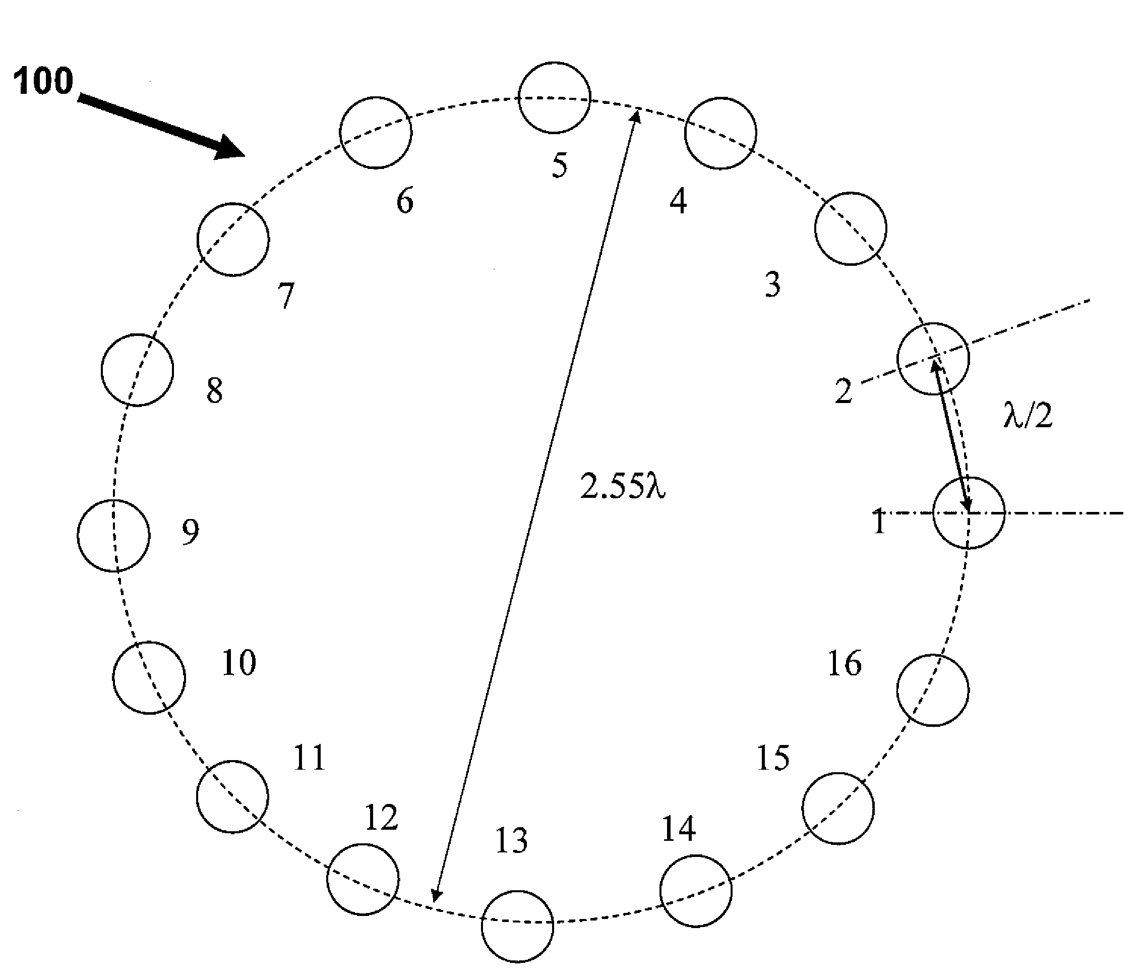
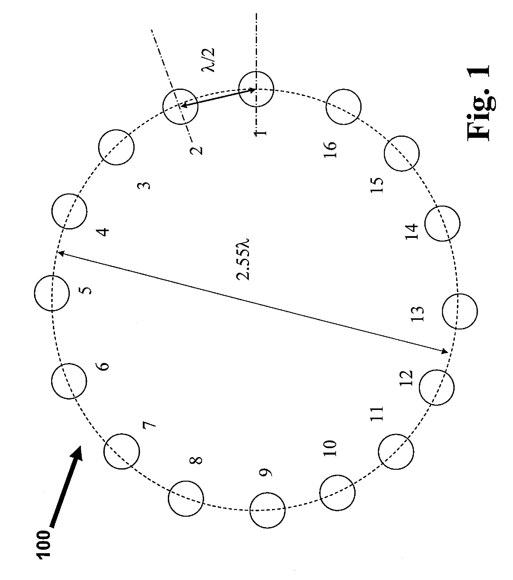
[0028]Referring to FIG. 1, which is a diagram, illustrates an exemplary array structure with 16 phased array elements of the present invention. The phased arrays are configured in a close loop in a circle or cylinder shape with diameter greater than the wavelength of the array element. For example, when 16 phased array elements are equipped in a circular configuration as shown FIG. 1, the ...


PUM


Abstract

The present invention provides an antenna array structure which includes multiple array elements, and the antenna array structure is using for the application of the WLAN (wireless local area network) or WMAN (wireless metro area network.) Furthermore, the array elements of the present invention are phased arrays or attenuated arrays, and when configuration with different type of the array element is used, the corresponding BFN (beam forming network) can also be implemented in various possibilities. With all the configuration of the present invention, the manufacturers can have a stable array structure for their applications.

Description

FIELD OF THE INVENTION[0001]The present invention relates to antenna array structure, and more particularly the present invention relates to antenna array structure for the application to wireless switch.BACKGROUND OF THE INVENTION[0002]Since the network services became an important part of daily life, the worldwide manufacturers of the network devices put all their attention to build a faster and stable network environment. Users generally divide the network into two different formats; one is wired network environment, and another is wireless network environment. In the field of the wired network environment, for example the Ethernet which is supported by huge numbers of network products, there are many well-defined products for public, so users can build up a reliable wired network environment with little efforts. However, the twisted network cables always bother users, and it looks uncomfortable for everyone. The introduction of the wireless network environment solves the botheri...

Claims


Application Information

Patent Timeline
Patent Type & Authority Patents(United States)
IPC IPC(8): H01Q21/00
CPCH01Q1/007H01Q21/20H01Q3/26H01Q1/246
Inventor LIU, I-RU
Owner ACCTON TECHNOLOGY CORPORATION
Why Eureka
Try Eureka