Thermally assisted magnetic recording head support mechanism

a technology of magnetic recording head and support mechanism, which is applied in the direction of combination recording, data recording, instruments, etc., can solve the problems of deterioration of the oscillation output of the recording head, and achieve the effects of reducing the weight of the slider, and reducing the loss of light transmission

Inactive Publication Date: 2008-06-05
HITACHI LTD
View PDF8 Cites 40 Cited by
  • Summary
  • Abstract
  • Description
  • Claims
  • Application Information

AI Technical Summary

Benefits of technology

[0015]The invention can provide a thermally assisted magnetic recording head support mechanism capable of holding back an increase in temperature of a heat source, due to heat generation by the heat source, and holding back an increase in weight of a slider while lessening transmission loss of light.

Problems solved by technology

Use of a laser diode (hereinafter referred to as an LD) as a light source for such a purpose is under study, however, an LD being a heat source as well as the light source, the LD has a problem in that oscillation output thereof undergoes deterioration, due to heat evolution of the LD itself.

Method used


Image

  • Thermally assisted magnetic recording head support mechanism
  • Thermally assisted magnetic recording head support mechanism
  • Thermally assisted magnetic recording head support mechanism

Examples


embodiment 1

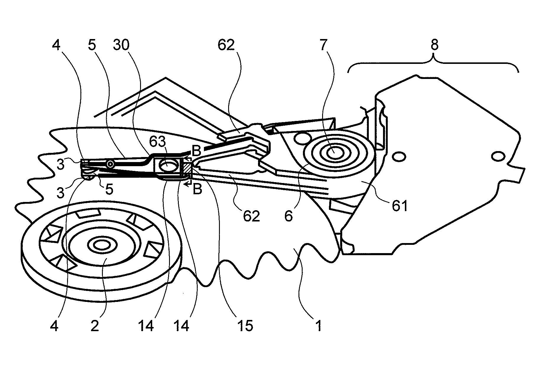
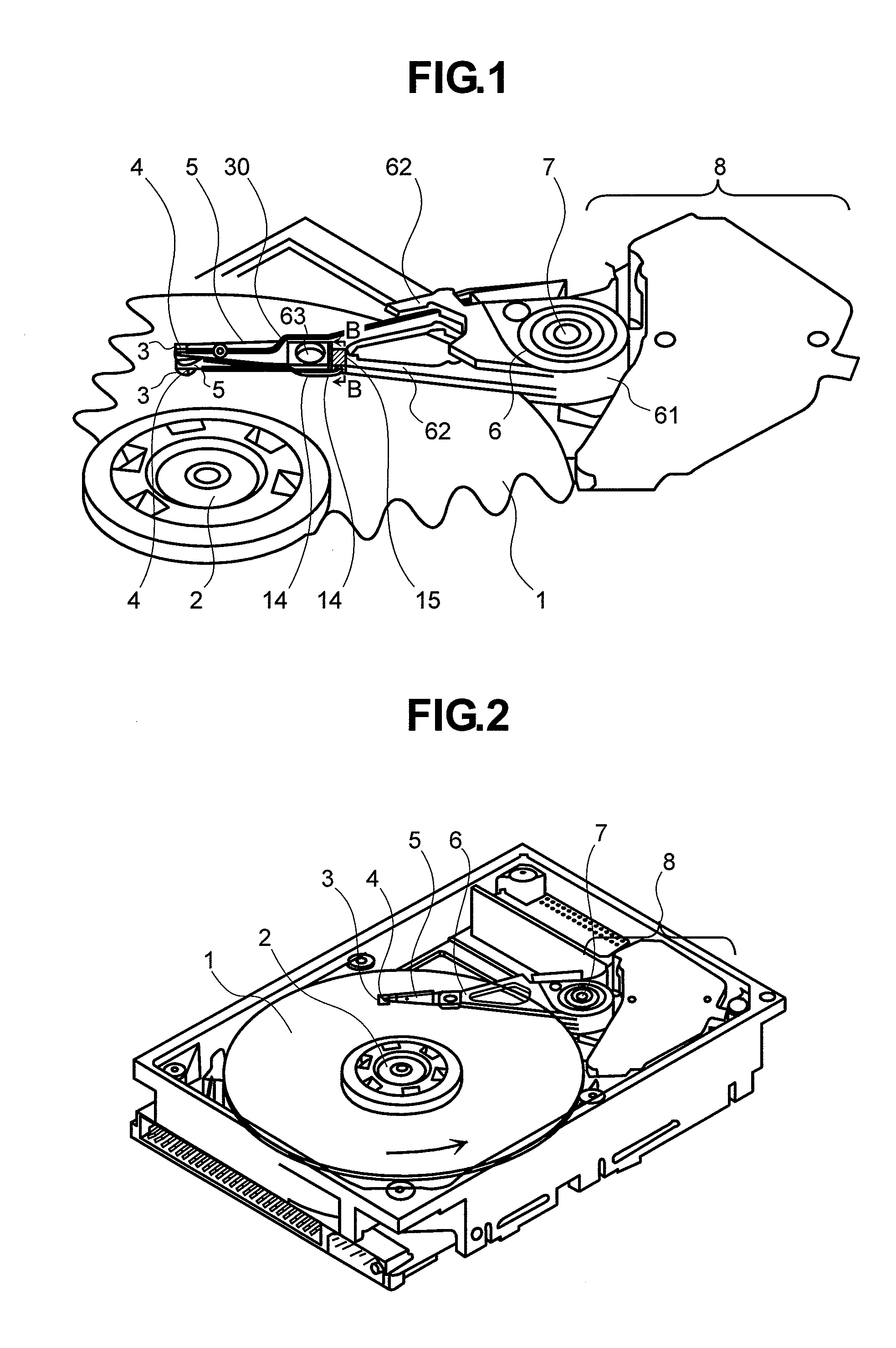
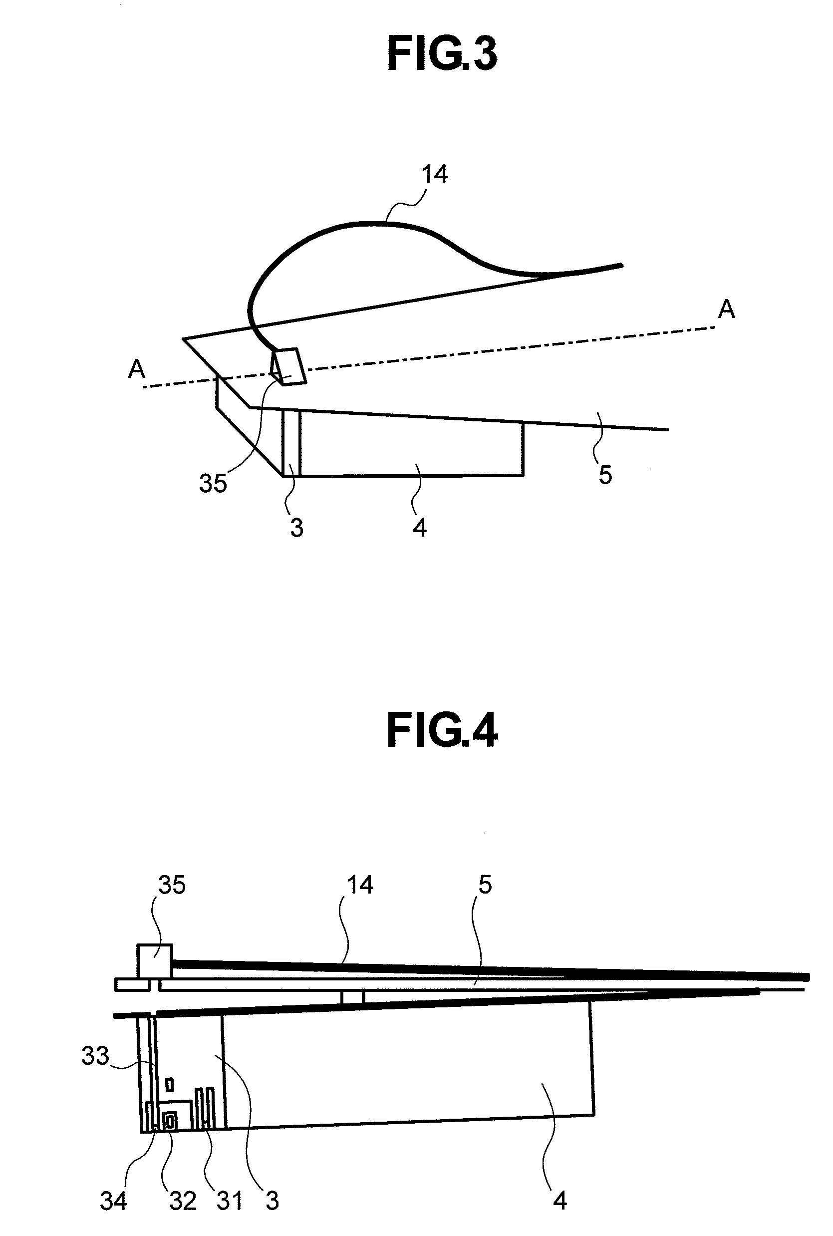
[0031]FIG. 1 shows an overall makeup of a thermally assisted magnetic recording head support mechanism according to Embodiment 1, FIG. 3 shows a peripheral part of the slider held by the suspension, and FIG. 4 shows the peripheral part, in section, taken on line A-A of FIG. 3.

[0032]In FIG. 1, the carriage 6 comprises a support 61 swingably supported by the pivot 7, and a plurality of arms 62 extending from the support 61. In FIG. 1, there is seen a second arm 62 from the topmost one, among the plurality of the arms 62. Two lengths of suspensions 5 are attached to the top and bottom surfaces of the tip of the arm 62, respectively, with a caulking fixture part 63. Interconnections 30 having one end connected to respective lead wires of a write element, and a read element of a magnetic head 3 are stacked up on the suspension 5, and the other end of each of the interconnections 30 is connected to a terminal area connected to a preamp (not shown). An optical bench 15 equipped with a ligh...

embodiment 2

[0047]FIG. 8 shows an overall makeup of a thermally assisted magnetic recording head support mechanism according to Embodiment 2. The overall makeup of a thermally assisted magnetic recording head support mechanism according to Embodiment 2 is the same as that for Embodiment 1, shown in FIG. 1. Embodiment 2 differs from Embodiment 1 only in respect of a mounting position of an optical bench 150, and an optical switching mechanism. Constituents of Embodiment 2, identical to those of Embodiment 1, are denoted by like reference numerals, and the constituents of the Embodiment 2, differing from those of Embodiment 1, are described hereinafter. In FIG. 8, the optical bench 150 is mounted in a support 61 of a carriage 6. Grooves are formed in the support 61 at the time of fabricating the carriage 6, and by fitting the optical bench 150 into the grooves, the optical bench 150 can be mounted in the support 61. Further, it is also possible to attach the optical bench 150 to the surface of th...


PUM

PropertyMeasurementUnit
electromagnetic attractive forceaaaaaaaaaa
swing angleaaaaaaaaaa
thermal conductivityaaaaaaaaaa

Abstract

[Problem] In a thermally assisted magnetic recording head support mechanism, an increase in the temperature of a heat source for supplying an optical near-field transducer with light, due to heat generation by the heat source, is checked while holding back an increase in weight of a slider and lessening transmission loss of light.[Solution] The thermally assisted magnetic recording head support mechanism is made up such that a suspension 5 has one end holding a slider 4 on which a magnetic head 3 having a read element 31, write element 32, and an optical near-field transducer 34 is mounted, and the other end of the suspension 5 is held by a carriage 6. The optical block 15 provided with one light source 10, and an optical switching mechanism capable of switching a guidance destination of irradiated light from light source 10 is attached to an arm 62 or a support 61 of the carriage 6 having a wide heat release area, thereby guiding light from the optical block 15 to the optical near-field transducer 34 via an optical waveguide 14.

Description

TECHNICAL FIELD[0001]The invention relates to a thermally assisted magnetic recording head support mechanism that can be mounted in a thermally assisted magnetic recording disk drive.BACKGROUND ART[0002]Thermally assisted recording is a scheme whereby data is recorded on a magnetic disk by applying heat at not lower than 200° C., together with a magnetic field, to a recording bit region of the order of several tens of nm in diameter, on the magnetic disk. Hopes run high that the thermally assisted recording is a recording scheme capable of high-density magnetic recording. As means for causing an instantaneous increase in temperature of a minute recording bit region on a magnetic disk, use of an optical near-field is under study at present. For generation of the optical near-field, it is necessary to introduce light into an optical near-field transducer disposed in the vicinity of a recording pole of a magnetic head. Use of a laser diode (hereinafter referred to as an LD) as a light ...

Claims


Application Information

Patent Timeline
Patent Type & Authority Applications(United States)
IPC IPC(8): G11B5/02
CPCG11B2005/0021G11B5/4826
Inventor NANIWA, IRIZOKATO, YUKIO
Owner HITACHI LTD
Why Eureka
Try Eureka