Electric utility system with superconducting magnetic energy storage

a superconducting magnetic and energy storage technology, applied in the field of electric power utility networks, can solve problems such as voltage instability on the utility power grid, voltage collapse, voltage instability on the grid, etc., and achieve the effect of stabilizing voltage and reducing transmission losses

Inactive Publication Date: 2005-06-14
AMERICAN SUPERCONDUCTOR
View PDF19 Cites 40 Cited by
  • Summary
  • Abstract
  • Description
  • Claims
  • Application Information

AI Technical Summary

Benefits of technology

[0017]The invention features an approach for stabilizing the voltage on a utility power system or network by reducing, during a fault recovery period, the overall real and reactive power losses of the utility power system. By “utility power system or network”, it is meant those systems or networks having at least one distribution line network coupled to a higher voltage transmission line network designed to carry a nominal voltage under normal operating conditions. The distribution line network generally includes at least one distribution feed having a load and carries voltages at levels lower than those on the transmission network. The invention reduces the transmission losses by delivering real and reactive power from a voltage recovery device at one or more predetermined locations on the utility power system.

Problems solved by technology

Voltage instability on the utility power grid is a critical problem for the utility industry.
In particular, when a fault occurs on the transmission grid, momentary voltage depressions are experienced, which may result in voltage collapse or voltage instability on the grid.
In general, such a fault appears as an extremely large load materializing instantly on the transmission system.
However, opening of the breakers triggers a sequence of cascading events, which in the extreme can cause voltage on that portion of the transmission and distribution system to collapse.
Specifically, when the breakers open, the voltage is still low (i.e., almost zero) and, because a portion of the transmission system has in effect been removed, the impedance of the system dramatically increases causing the appearance of an artificially high load.
The sharp increase in the current generates enormous losses in the transmission and distribution systems.
In some cases, because the load and impedance is so high, the voltage on the grid may not return to normal, causing long-term voltage depression and the possible voltage collapse of the entire system.
The potential for these voltage instability problems is further exacerbated as load requirements on the grid increase.
Although reactive volt-amperes, as such, require no average energy input to the generators their generation does consume a certain amount of generator volt-ampere capacity and thereby limits the available real power output of the generators.
In addition, there is a resistive or I2R loss associated with the transfer of reactive power over the grid.
This additional loss must also be made up by the generator and further limits the real power available to the grid.
However, providing such additional lines is expensive and in certain settings extremely difficult.

Method used


Image

  • Electric utility system with superconducting magnetic energy storage
  • Electric utility system with superconducting magnetic energy storage
  • Electric utility system with superconducting magnetic energy storage

Examples


Embodiment Construction

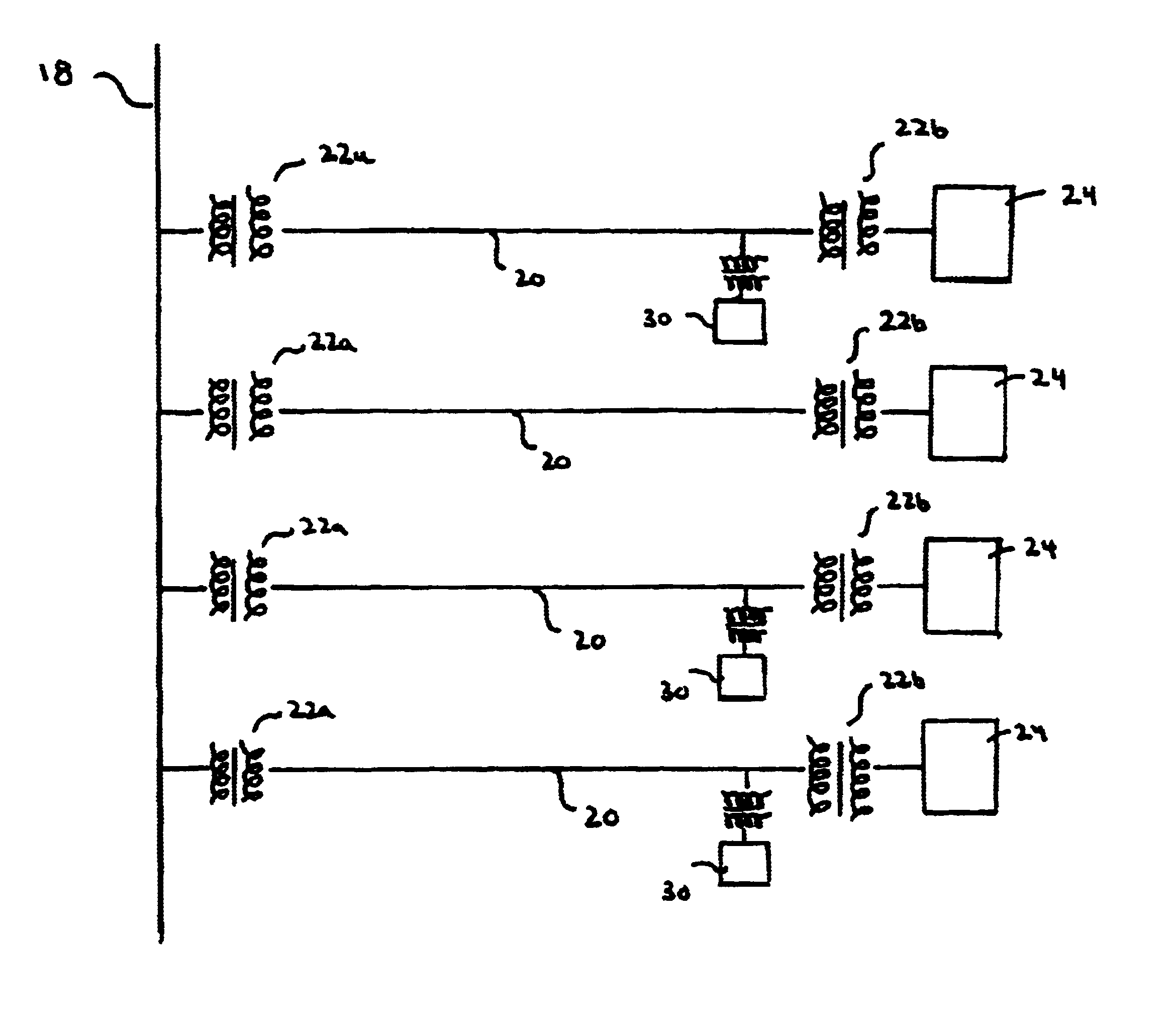
[0045]Referring to FIG. 4, a distributed SMES or D-SMES module 30 is shown connected in shunt with a distribution line 20 of a distribution line network. In general, D-SMES module 30 is capable of delivering both real and reactive power, separately or in combination, to a transmission line network. In this embodiment, D-SMES module 30 is sized at 2.8 MVA and is capable of delivering an average of 2 MWatts for periods as long as 400 milliseconds, 5.6 MVA for a full second, and 2.8 MVAR of reactive power indefinitely.

[0046]Distribution line 20 is shown connected to a transmission line 18 of the transmission line network through a first transformer 22a, which steps down the higher voltage (e.g., greater than 25 kV carried on transmission line 18 to a lower voltage, here 6kV. A second transformer 22b steps down the 6kV to a voltage suitable for a load 24, here 480 V.

[0047]D-SMES module 30 includes a superconducting magnetic energy storage unit 32 having an energy storage magnetic coil 3...


PUM


Abstract

a voltage recovery device is configured to provide real and reactive power to a utility power network at a sufficient level and for a sufficient duration to recover the voltage on the utility power network within a predetermined proportion of the nominal voltage, following a fault condition detected on the utility power network. Moreover, the voltage recovery device reduces the overall transmission losses in a utility power system.

Description

CROSS REFERENCE TO RELATED APPLICATIONS[0001]This application is a continuation-in-part of U.S. application Ser. No. 09 / 240,751, which was filed on Jan. 29, 1999, the entire contents of which are incorporated herein by reference. This application also claims priority under 35 U.S.C. §119(e)(1) U.S. application Ser. No. 60 / 117,784, filed Jan. 29, 1999.INCORPORATION BY REFERENCE[0002]This application herein incorporates by reference the following applications: (1) U.S. patent application Ser. No. 09 / 449,375, entitled “Method And Apparatus For Providing Power To A Utility Power Network”, filed on Nov. 24, 1999, now issued as U.S. Pat. No. 6,600,973; (2) U.S. patent application Ser. No. 09 / 449,376, entitled “Method And Apparatus For Controlling A Phase Angle”, filed on Nov. 24, 1999, now issued as U.S. Pat. No. 6,414,853; (3) U.S. Provisional Application No. 60 / 167,377, entitled “Voltage Regulation Of A Utility Power Network”, filed on Nov. 24, 1999; and (4) U.S. patent application Ser....

Claims


Application Information

Patent Timeline
Patent Type & Authority Patents(United States)
IPC IPC(8): H02J3/18H02J15/00H02J3/24H02J3/32
CPCH02J3/185Y02E40/67Y02E40/24Y02E40/10H02J3/32Y02E40/20Y02E40/60
Inventor KOEPPE, PAUL FREDERICKKEHRLI, ARNOLD P.DIAZ DE LEON, II, JOHN A.BROWN, DONALD L.BUCKLES, WARREN ELLIOTTFOLTS, DOUGLAS C.
Owner AMERICAN SUPERCONDUCTOR
Why Eureka
Try Eureka