Differential amplifier

a technology of amplifiers and amplifiers, applied in the field ofdifferential amplifiers, can solve problems such as difficult implementation of such amplifiers, and achieve the effects of reducing the forming area, stabilizing the voltage of floating nodes, and reducing the time for stabilizing them

Active Publication Date: 2016-06-21
HYUNDAI MOTOR CO LTD
View PDF11 Cites 0 Cited by
  • Summary
  • Abstract
  • Description
  • Claims
  • Application Information

AI Technical Summary

Benefits of technology

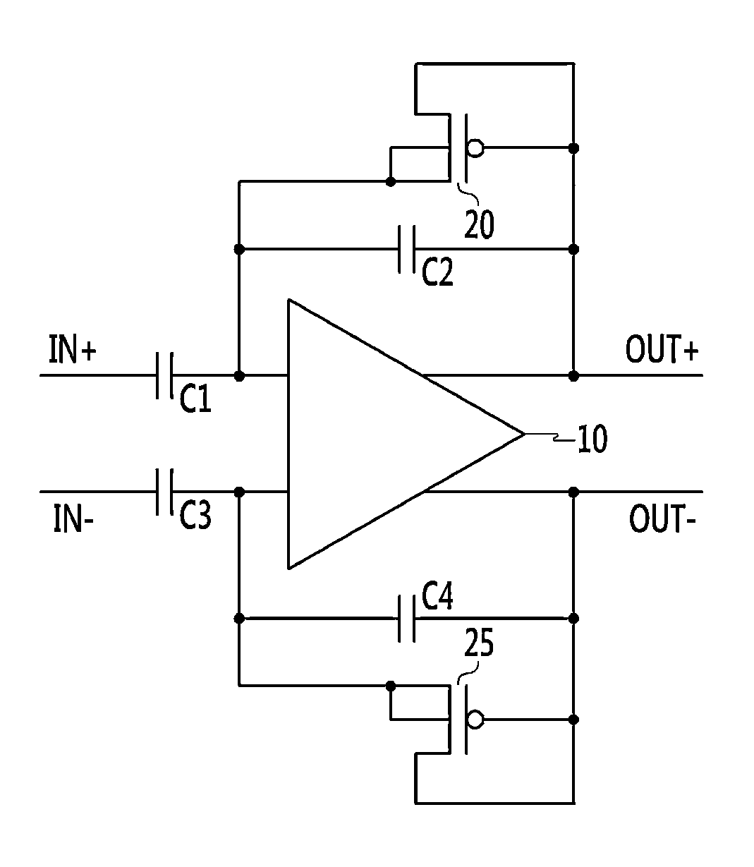
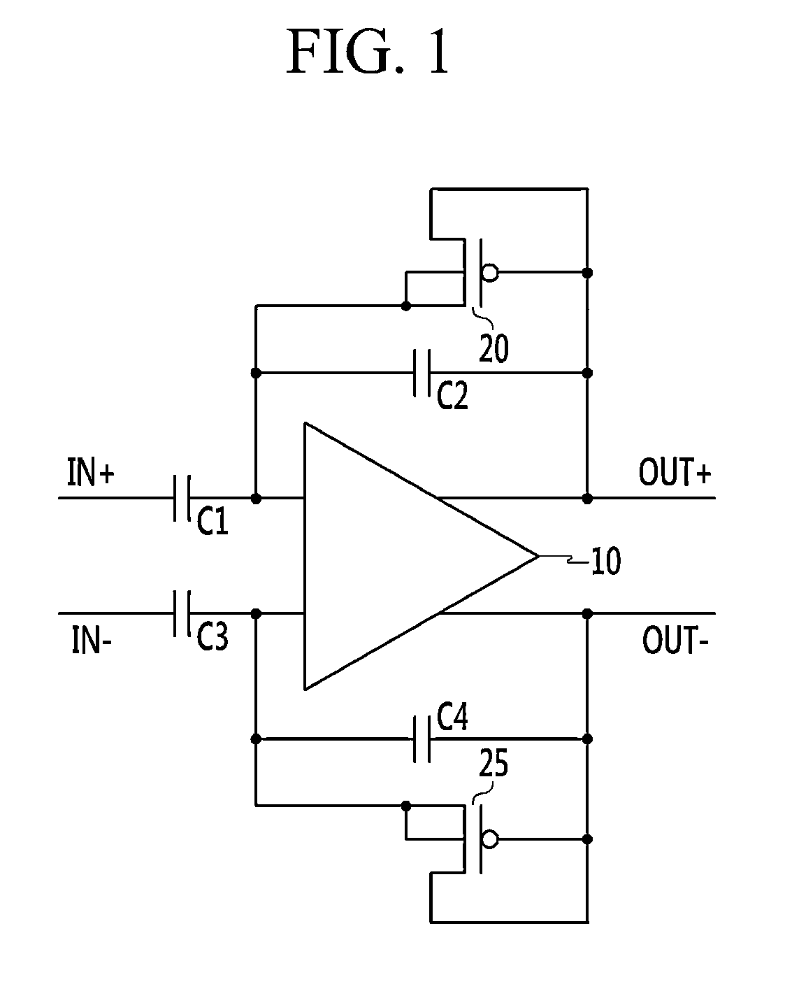
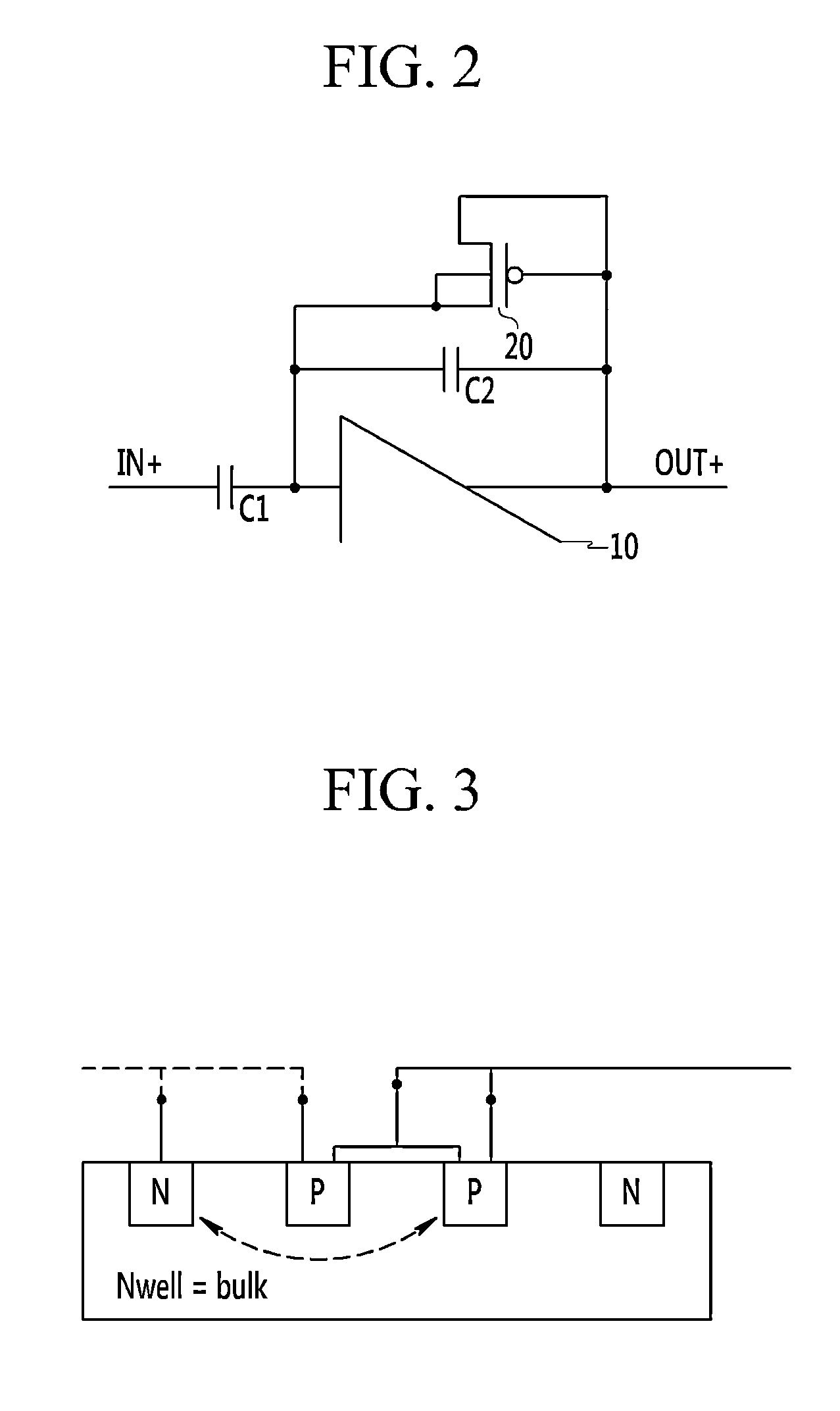
[0013]As described above, the four-terminal transistors may be formed in parallel with the capacitive feedback terminals of the differential amplifier, and one of source and drain terminals of each four-terminal transistor and the bulk terminal thereof may be connected to the floating node while the other two terminals may be connected to the output terminal of the differential amplifier, thereby stabilizing the voltages of the floating nodes and reducing the time for stabilizing them. In addition, elements used for stabilizing the floating node may be formed on the semiconductor substrate as the PMOS transistor, thereby reducing the forming area.

Problems solved by technology

Problems involved in differential amplifiers having a resistive feedback structure, include that a direct current (DC) offset is amplified in the output.
In particular, since the resistor having very high resistance does not affect the output of the amplifying terminal when the resistance is at least about 1 giga-ohm, a substantial area is required to acquire such a high resistance, thereby making implementation of such an amplifier difficult using a sub-micron complementary metal oxide semiconductor (CMOS) process.

Method used


Image

  • Differential amplifier
  • Differential amplifier
  • Differential amplifier

Examples


Embodiment Construction

[0021]It is understood that the term “vehicle” or “vehicular” or other similar term as used herein is inclusive of motor vehicles in general such as passenger automobiles including sports utility vehicles (SUV), buses, trucks, various commercial vehicles, watercraft including a variety of boats and ships, aircraft, and the like, and includes hybrid vehicles, electric vehicles, plug-in hybrid electric vehicles, hydrogen-powered vehicles and other alternative fuel vehicles (e.g. fuels derived from resources other than petroleum). As referred to herein, a hybrid vehicle is a vehicle that has two or more sources of power, for example both gasoline-powered and electric-powered vehicles.

[0022]Although exemplary embodiments are described as using a plurality of units to perform the exemplary process, it is understood that the exemplary processes may also be performed by one or plurality of modules. Additionally, it is understood that the term controller / control unit refers to a hardware de...


PUM


Abstract

Provided is a differential amplifier including: an operational amplifier (OP AMP) having an inverting input, a non-inverting input, an inverting output, and a non-inverting output, a first feedback capacitor connected to the non-inverting input and the inverting output. A second feedback capacitor connected to the inverting input and the non-inverting output, a first four-terminal transistor connected to the non-inverting input and the inverting output. A second four-terminal transistor connected to the inverting input and the non-inverting output. One of source and drain of the first transistor and a gate thereof are connected to the inverting output, the other one of the source and drain and a bulk terminal are connected to the non-inverting input, one of source and drain of the second transistor and a gate thereof are connected to the non-inverting output, and the other one of the source and drain terminals and a bulk terminal are connected to the inverting input.

Description

CROSS-REFERENCE TO RELATED APPLICATION(S)[0001]Pursuant to 35 U.S.C. §119(a), this application claims priority to Korean Patent Application No. 10-2013-0158648 filed on Dec. 18, 2013, the entire contents of which are incorporated herein by reference.BACKGROUND[0002]1. Field of the Invention[0003]The present invention relates to a differential amplifier, and more particularly, to a capacitive feedback fully-differential amplifier.[0004]2. Discussion of the Related Art[0005]Currently, amplifiers are being used in various electronic circuits, and such amplifiers may be used in various electronic devices. One type of amplifier used in such various electronic devices is a differential amplifier, which incorporates a resistive feedback structure and a capacitive feedback structure. Problems involved in differential amplifiers having a resistive feedback structure, include that a direct current (DC) offset is amplified in the output.[0006]In contrast, the capacitive feedback structure has ...

Claims


Application Information

Patent Timeline
Patent Type & Authority Patents(United States)
IPC IPC(8): H03F3/45
CPCH03F3/45475H03F2203/45511H03F2203/45512H03F2203/45528H03F2203/45544H03F3/45H03F3/45179
Inventor YANG, SANG-HYEOK
Owner HYUNDAI MOTOR CO LTD
Why Eureka
Try Eureka