

Washer fluid spraying apparatus
A technology of spraying device and cleaning fluid, which is applied in the direction of valve device, measuring device, vehicle cleaning, etc., can solve the problem of high manufacturing cost and achieve the effect of suppressing manufacturing cost
- Summary
- Abstract
- Description
- Claims
- Application Information
AI Technical Summary
Problems solved by technology
Method used
Image

Examples
Embodiment 1
[0021] according to Figure 1 ~ Figure 4 The cleaning liquid spraying device A of Example 1 which is the best embodiment of the present invention will be described.
[0022] First, its structure will be described.
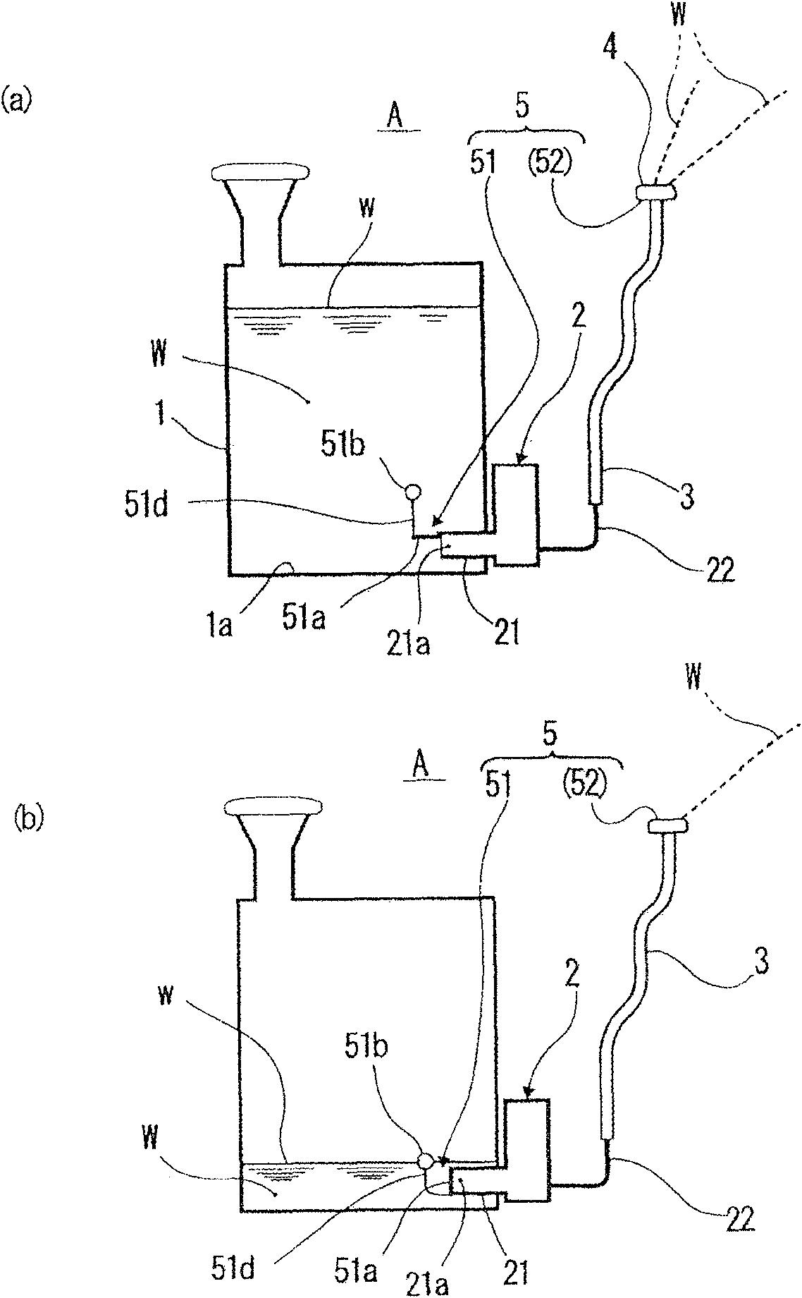
[0023] Such as figure 1 As shown, the washer liquid injection device A of Embodiment 1 includes a liquid tank 1 , a washer liquid pump 2 , a hose 3 , a washer liquid nozzle 4 , and a spray amount control device (residual amount notification device) 5 .
[0024] The tank 1 is used to store the washer fluid W, and is installed in an engine room (Japanese: Engineering Luim) or the like not shown in the figure.
[0025] Cleaning liquid pump 2 is installed in the bottom of liquid tank 1, utilizes motor 23 (referring to Figure 4 ) is driven to suck the cleaning liquid W from the suction pipe 21 and discharge it from the discharge pipe 22. In addition, a suction port 21 a at the tip of the suction pipe 21 opens near the bottom 1 a of the liquid tank 1 . Also, the wa...
Embodiment 2
[0045] The following is based on Figure 5 and Figure 6 A cleaning liquid spraying device according to Example 2 of the embodiment of the present invention will be described.
[0046] In addition, the same code|symbol is attached|subjected to the part which is the same as or equivalent to the said Example 1, and it demonstrates centering on a different part.
[0047] In the washer liquid spraying device of Embodiment 2, an elbow 251 is provided as suction amount limiting means (remaining amount notifying means).
[0048] The curved pipe 251 is arranged such that the opening 251a at one end thereof is disposed in the suction pipe 21, and the opening 251b at the other end is exposed on the liquid surface w of the cleaning liquid W when the remaining amount of the liquid tank is reduced to less than the set remaining amount. Roughly L-shaped.
[0049] In this second embodiment, the structure other than the inhalation amount limiting device is the same as that of the first emb...
Embodiment 3
[0059] The following is based on Figure 7 The cleaning liquid spraying device C of Example 3 of the embodiment of the present invention will be described.
[0060] In addition, the same code|symbol is attached|subjected to the part which is the same as or equivalent to other Example, and it demonstrates centering on a different part.
[0061] This Embodiment 3 is an example of an injection amount limiting device which employs the circulation switching device 330 as one form of the remaining amount notifying device.
[0062] The circulation switching device 330 has a return flow path 331 and a float valve (on-off valve) 332 .
[0063] The return path 331 is a pipe connecting the discharge pipe 322 on the discharge side of the cleaning liquid pump 302 and the liquid tank 301 , and a discharge nozzle for discharging the cleaning liquid W into the liquid tank 301 is provided at the opening end of the liquid tank side of the return path 331 . 333.
[0064] The float valve 332 i...
PUM
 Abstract
Description
Claims
Application Information