Liquid jet head and liquid jet apparatus

a liquid jet and apparatus technology, applied in the direction of printing, inking apparatus, etc., can solve the problems of deterioration of printing quality such as dot missing, and achieve the effect of preventing the reduction of an ejection stable zone and reducing the sectional area of the flow path

Inactive Publication Date: 2014-03-04
SII PRINTEK
View PDF9 Cites 0 Cited by
  • Summary
  • Abstract
  • Description
  • Claims
  • Application Information

AI Technical Summary

Benefits of technology

[0008]The present invention has been made in view of the above-mentioned problem, and has an object to provide a liquid jet head which is capable of preventing a printing stable zone from being narrowed, and preventing ejection characteristics from being deteriorated due to air bubble accumulation and the like.
[0019]With this structure, air bubbles and dust mixed into the liquid that has flowed into the flow path member flow via the circulation path to flow out from the outflow port. Further, no filter is interposed between the inflow port or the outflow port and the channel. Therefore, it is possible to provide a liquid jet head which is capable of preventing the air bubbles from accumulating to the filter to gradually reduce a flow path sectional area, and preventing an ejection stable zone from being reduced due to the pressure loss by the filter.

Problems solved by technology

Further, the air bubbles accumulated in the IN liquid chamber 204 may pass through the head filter 203 to flow into the nozzle liquid chamber 202, which may cause deterioration of printing quality such as dot missing.

Method used


Image

  • Liquid jet head and liquid jet apparatus
  • Liquid jet head and liquid jet apparatus
  • Liquid jet head and liquid jet apparatus

Examples


first embodiment

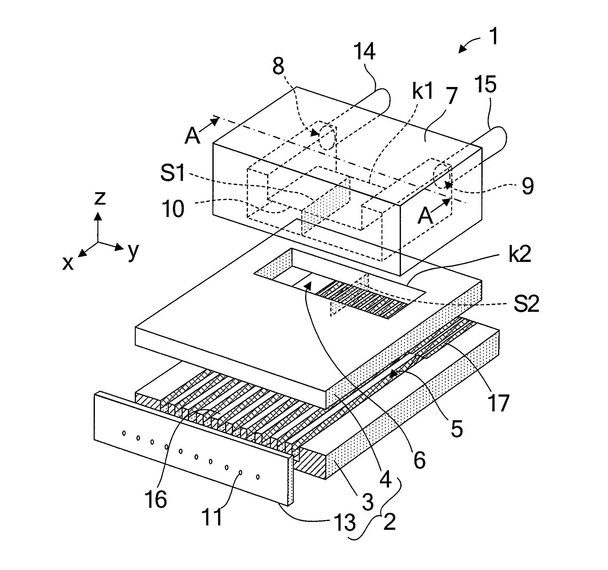
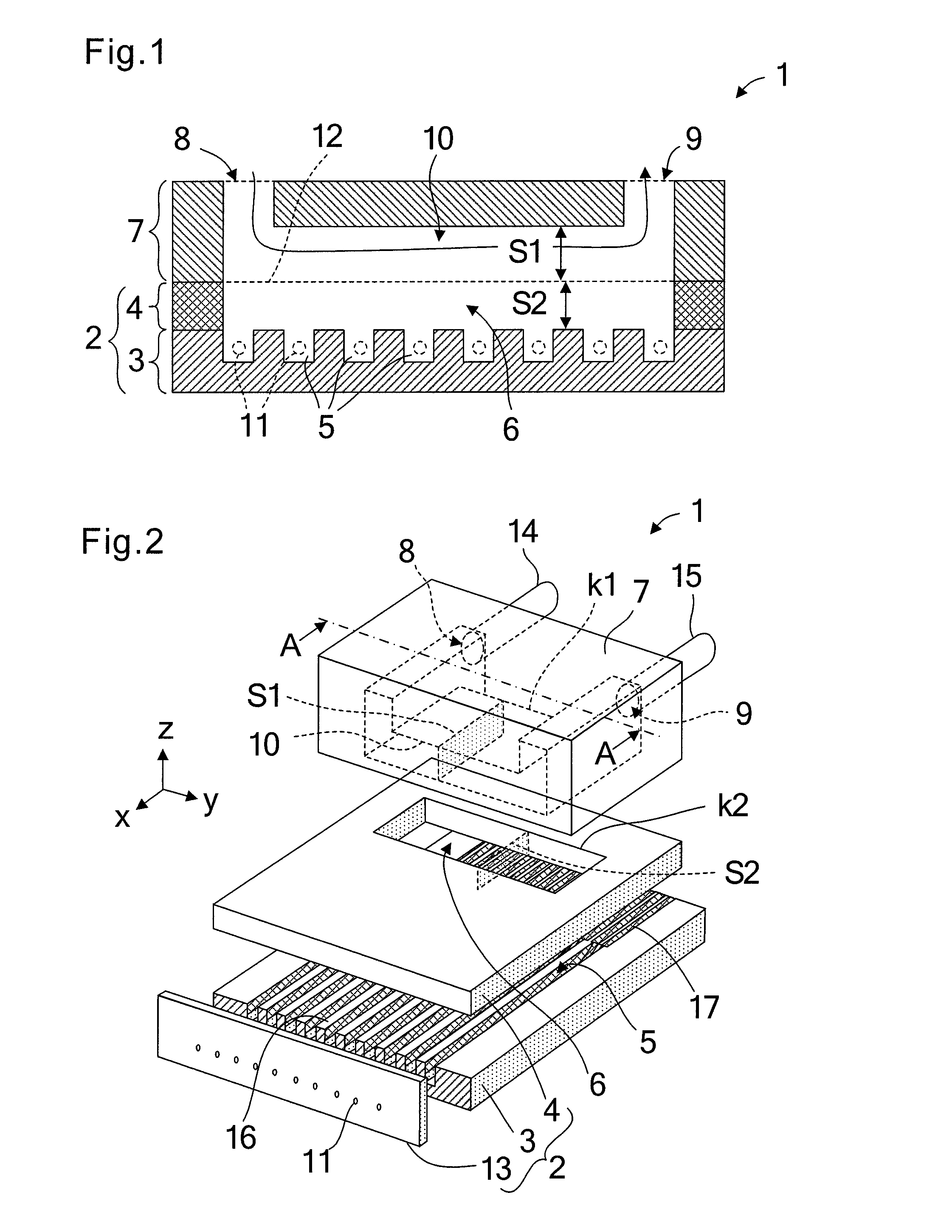
[0036]FIG. 2 is a schematic exploded perspective view of a liquid jet head 1 according to a first embodiment of the present invention. As illustrated in FIG. 2, the liquid jet head 1 includes an actuator substrate 3, a cover plate 4 bonded on the actuator substrate 3, and a flow path member 7 bonded on the cover plate 4. A large number of parallel grooves are formed in the surface of the actuator substrate 3. The cover plate 4 and the actuator substrate 3 are bonded to each other to form channels 5. On respective front end surfaces of the actuator substrate 3 and the cover plate 4, a nozzle plate 13 having nozzles 11 communicated to the respective channels 5 is bonded.

[0037]A liquid supply chamber 6 is provided in the cover plate 4 on a rear side thereof. The liquid supply chamber 6 is communicated to rear ends of the respective channels 5 so that liquid can be supplied to the respective channels 5. The liquid supply chamber 6 is opened on the flow path member 7 side. On the respect...

second embodiment

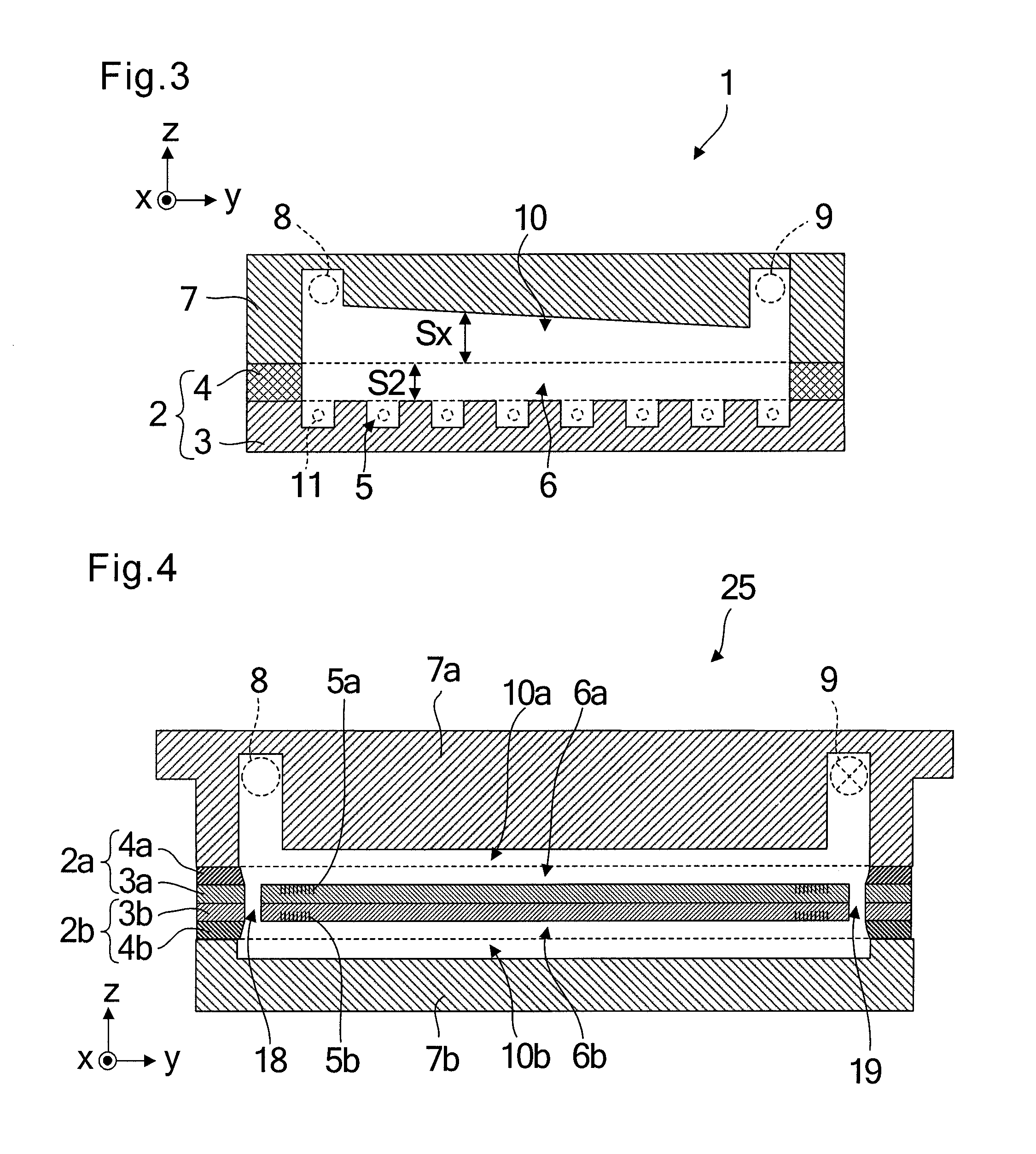
[0045]FIG. 3 is a schematic vertical sectional view of a liquid jet head 1 according to a second embodiment of the present invention, which corresponds to a vertical cross-section taken along the line A-A illustrated in FIG. 2. A part different from the first embodiment is the shape of the circulation path 10 formed in the flow path member 7. Other parts are similar to those of the first embodiment.

[0046]As illustrated in FIG. 3, the liquid jet head 1 has a structure in which the actuator substrate 3, the cover plate 4, and the flow path member 7 are stacked. The actuator substrate 3 has an upper surface in which the plurality of channels 5 are arranged in parallel to each other, and the respective channels 5 are communicated to the liquid supply chamber 6 formed in the cover plate 4. The head chip 2 is formed of the actuator substrate 3 and the cover plate 4.

[0047]The flow path member 7 includes the circulation path 10 opened on the surface thereof on the head chip 2 side, and also...

third embodiment

[0049]FIGS. 4 and 5 are views illustrating a liquid jet head 1 according to a third embodiment of the present invention. FIG. 4 is a schematic vertical sectional view of a head chip portion 25, and FIG. 5 is a perspective view of the liquid jet head 1 in which the head chip portion 25 is assembled to a base member 21. The same parts and parts having the same functions as those in the above-mentioned embodiments are denoted by the same reference symbols.

[0050]As illustrated in FIG. 4, in the head chip portion 25, a first head chip 2a and a second head chip 2b have a symmetric structure in which an actuator substrate 3a of the first head chip 2a and an actuator substrate 3b of the second head chip 2b are opposed and bonded to each other. That is, the first head chip 2a includes the actuator substrate 3a and a cover plate 4a bonded to each other. The actuator substrate 3a has a surface having channels 5a for liquid ejection formed therein. The cover plate 4a includes a liquid supply ch...


PUM


Abstract

A head chip includes an actuator substrate having channels for liquid ejection formed therein, and a cover plate having a liquid supply chamber for supplying liquid to the channels, the cover plate being stacked on the actuator substrate. A flow path member mounted to the cover plate supplies the liquid to the liquid supply chamber. The flow path member includes an inflow port through which the liquid flows in, an outflow port through which the liquid flows out, and a circulation path along which the liquid is circulated from the inflow port to the outflow port. No filter is interposed in either the flow path between the inflow port and the channels or the flow path between the outflow port and the channels. The sectional area of the circulation path in a direction orthogonal to the circulating direction of liquid flow is larger than that of the liquid supply chamber.

Description

BACKGROUND OF THE INVENTION[0001]1. Field of the Invention[0002]The present invention relates to a liquid jet head which ejects liquid from nozzles to form images and letters on a recording medium or to form a thin film material, and a liquid jet apparatus using the same.[0003]2. Description of the Related Art[0004]In recent years, there has been used an ink jet type liquid jet head which ejects ink droplets onto recording paper and the like to draw letters and diagrams, or ejects a liquid material onto a surface of an element substrate to form a functional thin film. The liquid jet head of this type is supplied with ink or a liquid material from a liquid tank via a supply tube, and is caused to eject the ink or the liquid material filled in channels thereof from nozzles communicated to the channels. At the time of ink ejection, the liquid jet head and a recording medium for recording the jetted liquid are moved, to thereby record the letters and diagrams or form the functional thin...

Claims


Application Information

Patent Timeline
Patent Type & Authority Patents(United States)
IPC IPC(8): B41J2/18B41J2/05
CPCB41J2202/07B41J2/18B41J2202/12B41J2/17563B41J2202/11B41J2/14209B41J2002/14419
Inventor SAKATA, AKIFUMIDOMAE, YOSHINORI
Owner SII PRINTEK
Why Eureka
Try Eureka