Liquid jet head and liquid jet apparatus
- Summary
- Abstract
- Description
- Claims
- Application Information
AI Technical Summary
Benefits of technology
Problems solved by technology
Method used
Image
Examples
first embodiment
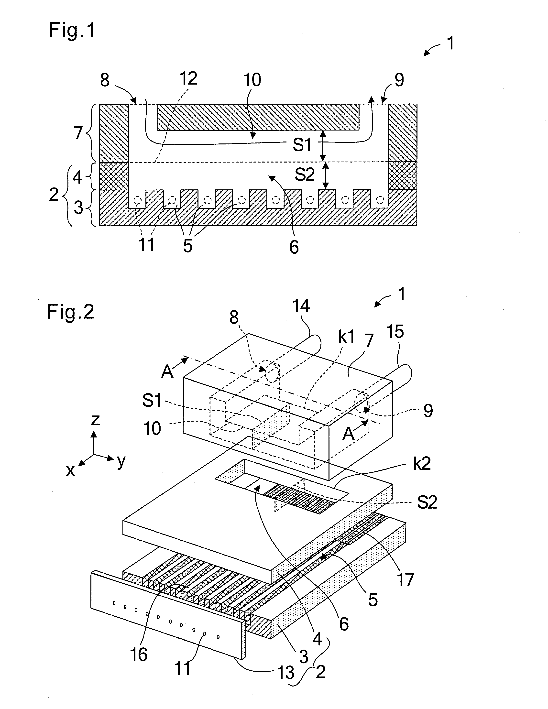
[0036]FIG. 2 is a schematic exploded perspective view of a liquid jet head 1 according to a first embodiment of the present invention. As illustrated in FIG. 2, the liquid jet head 1 includes an actuator substrate 3, a cover plate 4 bonded on the actuator substrate 3, and a flow path member 7 bonded on the cover plate 4. A large number of parallel grooves are formed in the surface of the actuator substrate 3. The cover plate 4 and the actuator substrate 3 are bonded to each other to form channels 5. On respective front end surfaces of the actuator substrate 3 and the cover plate 4, a nozzle plate 13 having nozzles 11 communicated to the respective channels 5 is bonded.
[0037]A liquid supply chamber 6 is provided in the cover plate 4 on a rear side thereof. The liquid supply chamber 6 is communicated to rear ends of the respective channels 5 so that liquid can be supplied to the respective channels 5. The liquid supply chamber 6 is opened on the flow path member 7 side. On the respect...
second embodiment
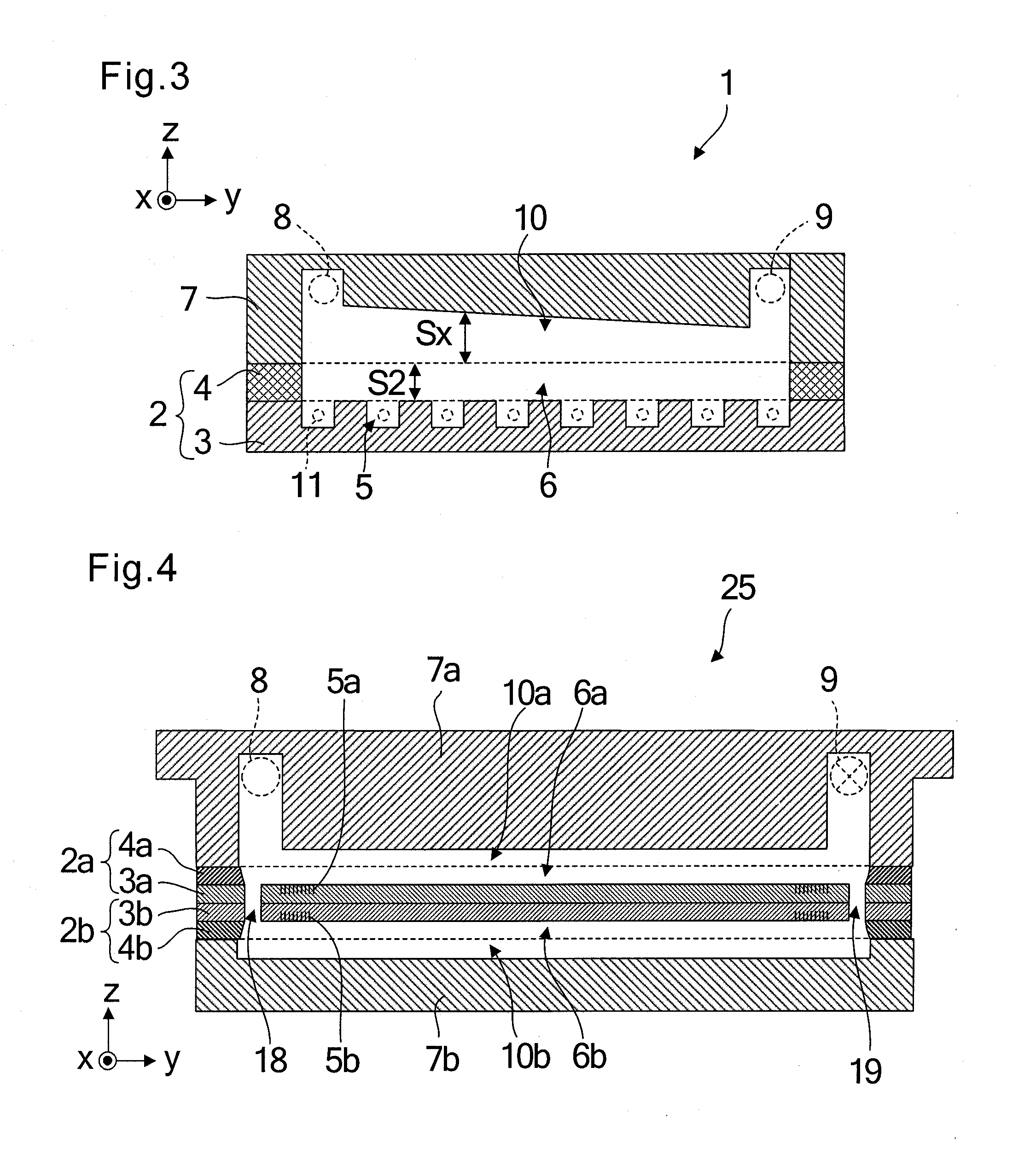
[0045]FIG. 3 is a schematic vertical sectional view of a liquid jet head 1 according to a second embodiment of the present invention, which corresponds to a vertical cross-section taken along the line A-A illustrated in FIG. 2. A part different from the first embodiment is the shape of the circulation path 10 formed in the flow path member 7. Other parts are similar to those of the first embodiment.
[0046]As illustrated in FIG. 3, the liquid jet head 1 has a structure in which the actuator substrate 3, the cover plate 4, and the flow path member 7 are stacked. The actuator substrate 3 has an upper surface in which the plurality of channels 5 are arranged in parallel to each other, and the respective channels 5 are communicated to the liquid supply chamber 6 formed in the cover plate 4. The head chip 2 is formed of the actuator substrate 3 and the cover plate 4.
[0047]The flow path member 7 includes the circulation path 10 opened on the surface thereof on the head chip 2 side, and also...
third embodiment
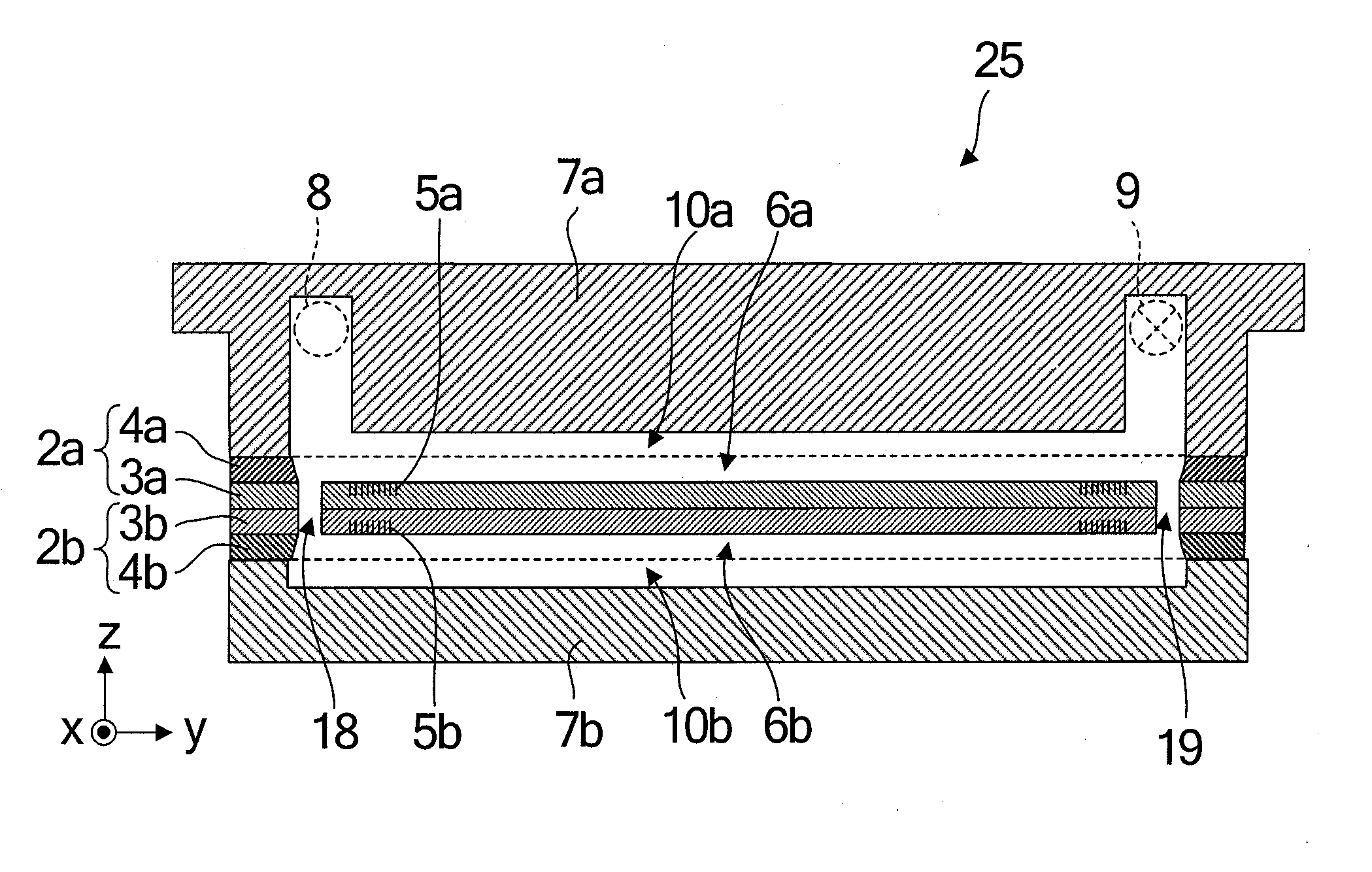
[0049]FIGS. 4 and 5 are views illustrating a liquid jet head 1 according to a third embodiment of the present invention. FIG. 4 is a schematic vertical sectional view of a head chip portion 25, and FIG. 5 is a perspective view of the liquid jet head 1 in which the head chip portion 25 is assembled to a base member 21. The same parts and parts having the same functions as those in the above-mentioned embodiments are denoted by the same reference symbols.
[0050]As illustrated in FIG. 4, in the head chip portion 25, a first head chip 2a and a second head chip 2b have a symmetric structure in which an actuator substrate 3a of the first head chip 2a and an actuator substrate 3b of the second head chip 2b are opposed and bonded to each other. That is, the first head chip 2a includes the actuator substrate 3a and a cover plate 4a bonded to each other. The actuator substrate 3a has a surface having channels 5a for liquid ejection formed therein. The cover plate 4a includes a liquid supply ch...
PUM
 Abstract
Description
Claims
Application Information
 - R&D
- Intellectual Property
- Life Sciences
- Materials
- Tech Scout
- Unparalleled Data Quality
- Higher Quality Content
- 60% Fewer Hallucinations
Browse by: Latest US Patents, China's latest patents, Technical Efficacy Thesaurus, Application Domain, Technology Topic, Popular Technical Reports.
© 2025 PatSnap. All rights reserved.Legal|Privacy policy|Modern Slavery Act Transparency Statement|Sitemap|About US| Contact US: help@patsnap.com


