Elastic abrasive manufacturing method, elastic abrasive manufacturing device, blasting method, and blasting device

a manufacturing method and elastic abrasive technology, applied in the direction of manufacturing tools, other chemical processes, chemistry apparatus and processes, etc., can solve the problems of large difference in surface state, unstable cutting rate, and gradual decrease of cutting performance of elastic abrasives

Active Publication Date: 2021-08-26
FUJI MFG CO LTD
View PDF1 Cites 1 Cited by
  • Summary
  • Abstract
  • Description
  • Claims
  • Application Information

AI Technical Summary

Benefits of technology

[0057]FIG. 10 is an explanatory diagram illustrating a relationship between eject

Problems solved by technology

This means that when blasting is performed using an elastic abrasive in a re-circulatory type blasting device, as illustrated in FIG. 10, the cutting performance of the elastic abrasive gradually decreases with the passage of time, resulting in a large difference arising in surface state, such as glossiness or mirror finish, between a state of treatment of a workpiece when treatment was performed employing the elastic abrasive in a new state, and a state of treatment of a workpiece when treatment was performed employing the elastic abrasive that has already been used repeatedly.
The cuttin

Method used


Image

  • Elastic abrasive manufacturing method, elastic abrasive manufacturing device, blasting method, and blasting device
  • Elastic abrasive manufacturing method, elastic abrasive manufacturing device, blasting method, and blasting device
  • Elastic abrasive manufacturing method, elastic abrasive manufacturing device, blasting method, and blasting device

Examples


example

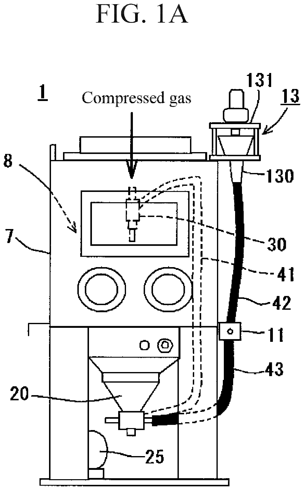
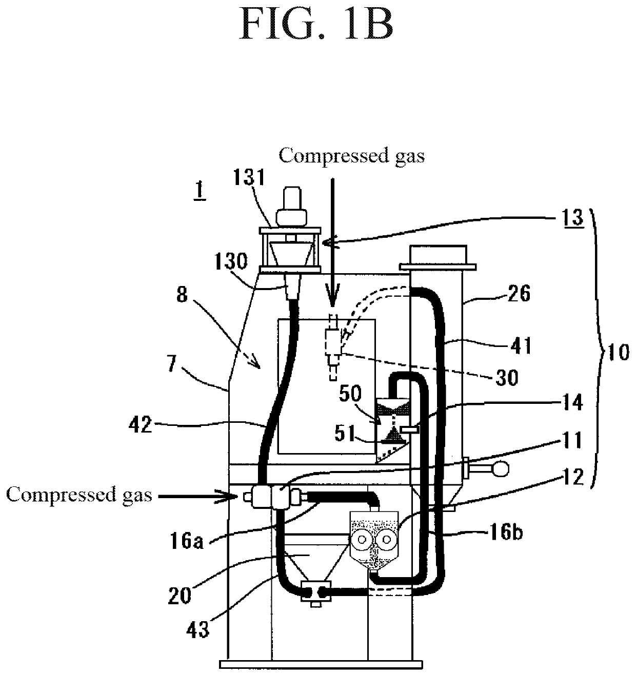
[0140]Description follows regarding the results of tests performed to check the performance of the blasting device of the present invention equipped with the elastic abrasive regeneration device.

[0141]Test Aims

[0142]The aim of the tests was to confirm that there was no reduction in cutting performance when performing blasting using the blasting device of the present invention equipped with the elastic abrasive regeneration device, and to confirm that stable cutting performance could be obtained for a prolonged period of time therewith.

[0143]Test Method

[0144]The elastic abrasive employed was configured by cores made of an elastomer with self-adhesive properties (having an average major axis dimension of from 0.3 mm to 1.0 mm), with 10000 grit (D50: 0.6 μm) diamond abrasive grains adhered to the surface thereof at an amount of 30% by weight relative to the cores (“Series Z” manufactured by Fuji Manufacturing Co., Ltd).

[0145]The blasting device employed in the Example was based on a co...


PUM

PropertyMeasurementUnit
Flow rateaaaaaaaaaa
Adhesivityaaaaaaaaaa
Areaaaaaaaaaaa

Abstract

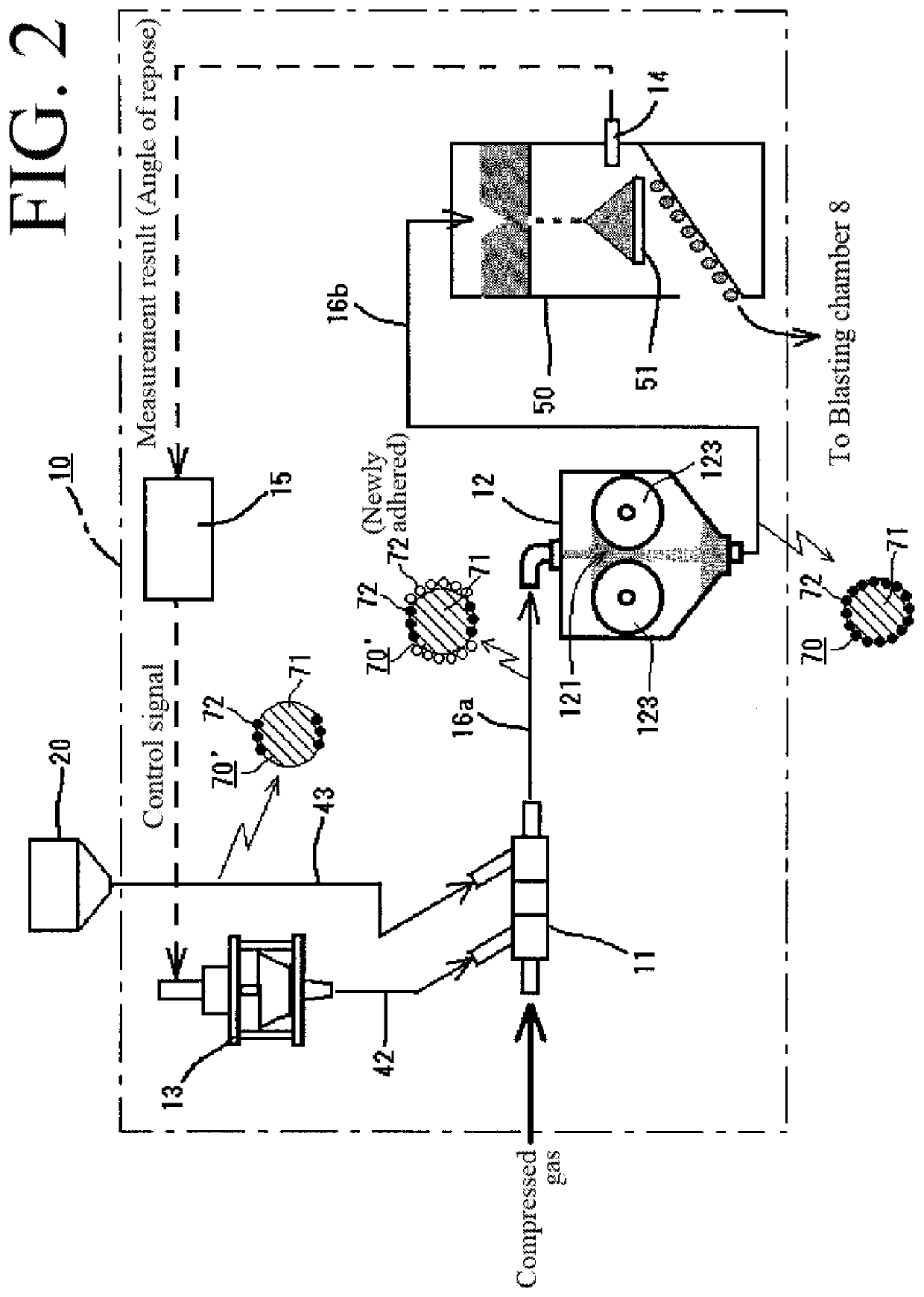
A re-circulatory blasting device obtained is capable of performing stable treatment for a prolonged period of time even in cases in which an elastic abrasive employed has abrasive grains adhered to the surface of elastic cores. An elastic abrasive regeneration device provided to the blasting device regenerates elastic abrasive employed for re-circulation. The elastic abrasive regeneration device includes a mixer and a combining unit. Recovered abrasive fed in from an abrasive recovery section is mixed in the mixer with abrasive grains fed in from an abrasive grain feeder, and the abrasive grains are adhered to the surface of the cores of the recovered abrasive. In the combining unit, the abrasive grains are pressed against and combined to the surface of the cores by passing an aggregated state of the recovered abrasive mixed by the mixer along a constricted flow path having a flow path cross-sectional area that gradually narrows.

Description

BACKGROUND OF THE INVENTION1. Field of the Invention[0001]The present invention relates to a method for manufacturing an elastic abrasive, to an elastic abrasive manufacturing device, to a blasting method, and to a blasting device. In particular the present invention relates to a method for manufacturing an elastic abrasive having a structure in which abrasive grains have been adhered to the surface of elastic cores, to an elastic abrasive manufacturing device to execute the manufacturing method, and to a re-circulatory blasting method or blasting device of a configuration that includes the elastic abrasive manufacturing method or manufacturing device to regenerate elastic abrasive employed in re-circulation.[0002]Note that “manufacturing” of the elastic abrasive in the present invention includes, in addition to adhering abrasive grains to the surface of unused cores, “regeneration” in which cores of elastic abrasive in a state in which abrasive grains have become detached from the ...

Claims


Application Information

Patent Timeline
IPC IPC(8): B24C5/02B24C3/08B24C9/00
CPCB24C5/02B24C7/0046B24C9/003B24C3/083B24C11/00B24C3/04B24C5/04B24C9/00B24C9/006C09K3/1436Y02P70/10B29C70/00
Inventor MASE, KEIJIISHIBASHI, SHOZOKITAGAMI, MASATOSHI
Owner FUJI MFG CO LTD
Why Eureka
Try Eureka