
System for real-time monitoring of fatigue of driver of automobile

A real-time monitoring system and driver fatigue technology, applied in diagnostic recording/measurement, medical science, sensors, etc., can solve problems such as single means of human body information and inability to collect relevant information, and achieve the effect of improving reliability

Inactive Publication Date: 2007-07-25
武汉交通科技研究院有限责任公司
View PDF1 Cites 33 Cited by
  • Summary
  • Abstract
  • Description
  • Claims
  • Application Information

AI Technical Summary

Problems solved by technology

[0004] The above-mentioned "human body information monitoring steering wheel" has a simple structure and low cost, but the means of collecting human body information is single, and it is impossible to comprehensively collect various relevant information on the driver's tired human body

Method used


Image

  • System for real-time monitoring of fatigue of driver of automobile
  • System for real-time monitoring of fatigue of driver of automobile

Examples


Embodiment Construction

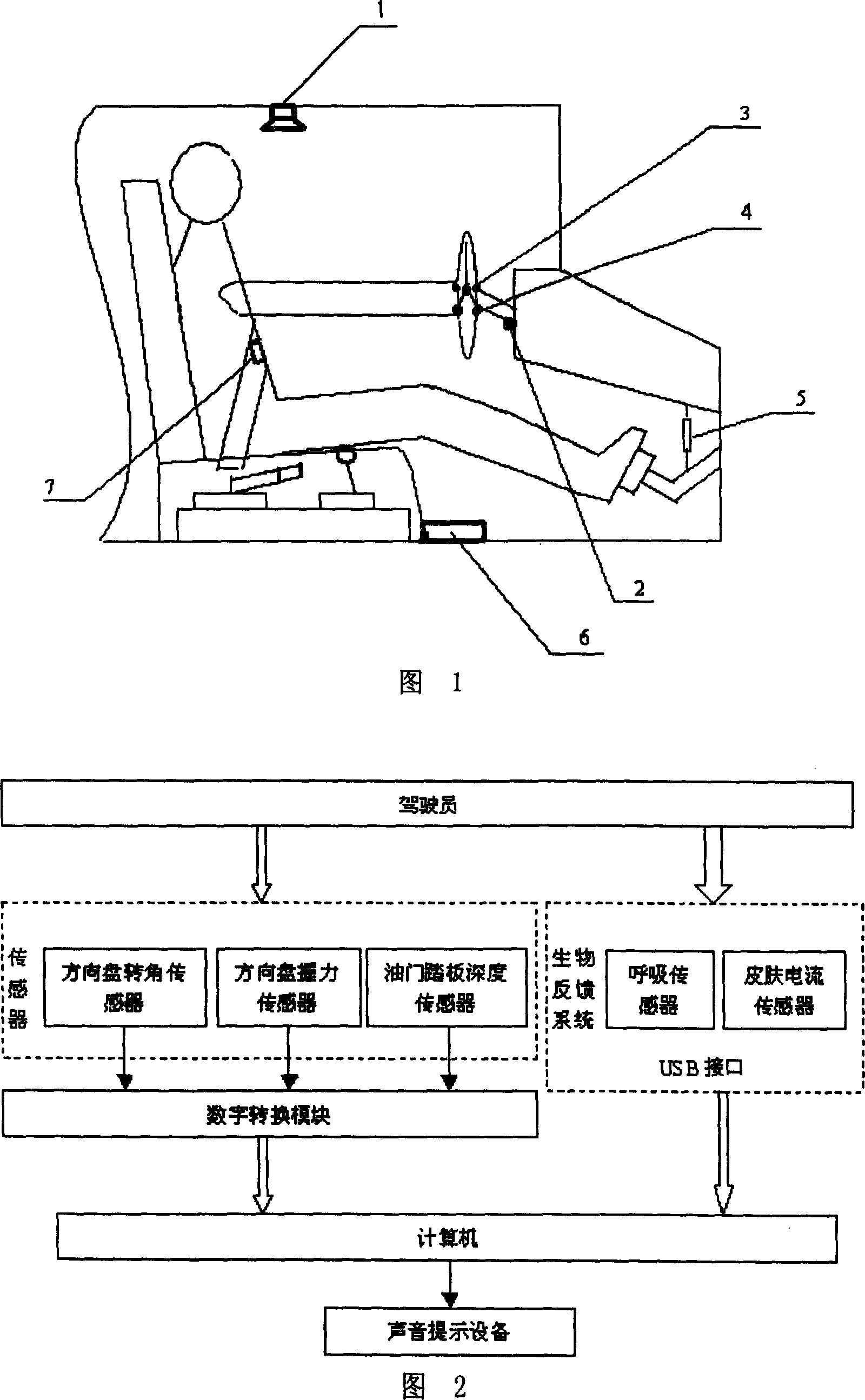
[0022] Embodiment of the present invention as shown in Figure 1, it is the long-distance bus driver fatigue real-time monitoring system. It includes an on-board computer 6, an accelerator pedal depth sensor 5, a breathing sensor 7 for measuring the driver's breathing rate and breathing depth, a skin current sensor 4, a steering wheel angle sensor 2, a steering wheel grip sensor 3, and an audio prompt device.

[0023] The accelerator pedal depth sensor 5 is arranged between the car body and the accelerator pedal; the breathing sensor 7 is arranged on the safety belt 2 at the contact position with the upper torso of the human body; Hand contact; the steering wheel angle sensor 2 is installed between the steering wheel steering shaft and the vehicle body.

[0024] As shown in Figure 2, the signal output ends of the accelerator pedal depth sensor 5, the steering wheel grip sensor 3, and the steering wheel angle sensor 2 are all connected to the signal input end of the on-board com...


PUM


Abstract

A real-time monitor system for the fatigue degree of car driver is composed of a car carried computer, a throttle pedal depth sensor, and a respiratory sensor for the car driver to measure its respiratory frequency and depth.

Description

technical field [0001] The invention relates to automobiles, in particular to a real-time monitoring system on the automobile, especially a monitoring system for real-time monitoring of the physical condition of the driver of the automobile. Background technique [0002] Driver fatigue driving is one of the important reasons leading to vicious traffic accidents, especially in long-distance bus traffic accidents, the harmfulness of fatigue driving is the most prominent. Long-distance bus drivers drive for a long time and have heavy workloads, which can easily cause driving fatigue and even traffic accidents. Due to the large number of passengers in the vehicle or the large number of goods in the vehicle, once a traffic accident occurs, it will cause disastrous consequences. According to the report of the U.S. National Traffic Safety Department in 1990, heavy 31% of the traffic accidents that caused the death of heavy truck drivers were related to fatigue driving. The statis...

Claims


Application Information

Patent Timeline
IPC IPC(8): A61B5/18
Inventor 吴超仲马明严新平高嵩毛喆
Owner 武汉交通科技研究院有限责任公司
Learn More