Levelling equipment for vacuum chamber

A technology of leveling devices and vacuum chambers, applied in the field of leveling devices, can solve problems affecting production scheduling and occupancy of cranes, and achieve the effects of improving production efficiency, speeding up adjustment time, and simplifying adjustment operations

Inactive Publication Date: 2007-07-25
WISDRI ENG & RES INC LTD
View PDF0 Cites 2 Cited by
  • Summary
  • Abstract
  • Description
  • Claims
  • Application Information

AI Technical Summary

Problems solved by technology

[0004] When adjusting the gasket set, the vacuum chamber needs to be hoisted by a crane, and then the thickness of the gasket is select

Method used


Image

  • Levelling equipment for vacuum chamber
  • Levelling equipment for vacuum chamber
  • Levelling equipment for vacuum chamber

Examples


Example Embodiment

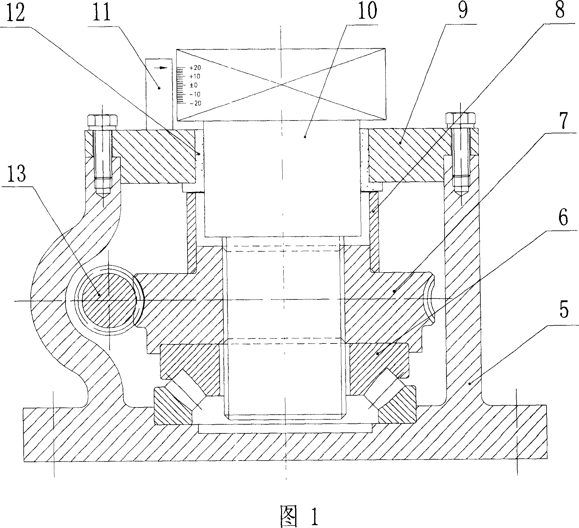
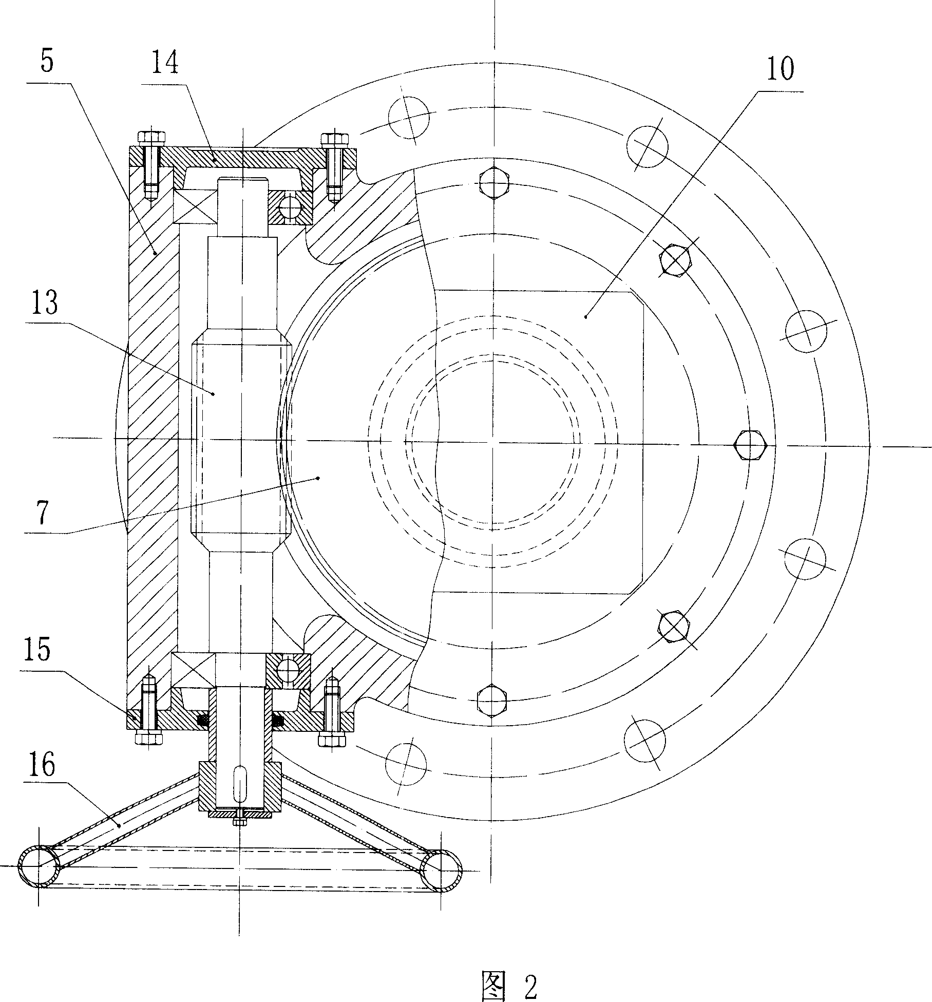
[0015] As shown in Figure 1 and Figure 2, the vacuum chamber leveling device includes a box body 5, a thrust bearing 6, a worm gear 7, a shaft sleeve 8, a guide cover 9, a screw support 10, a limit block 11, a sliding bearing 12, Worm 13, stuffy cover 14, transparent cover 15. The box body 5 is a cavity, the upper end of the box body 5 is an opening, the guide cover 9 is provided with a guide hole, and the lower part of the screw support 10 passes through the guide hole on the guide cover 9 And located in the cavity of the box body 5, the thrust bearing 6, the worm gear 7 are respectively located in the cavity of the box body 5, the worm wheel 7 is located above the thrust bearing 6, the lower end of the worm wheel 7 is formed by the thrust bearing 6 and the box body 5Fixed connection, the screw post 10 is provided with an external thread, the worm wheel 7 is provided with an internal thread hole, the screw post 10 is screwed into the internal thread hole of the worm wheel 7, and ...


PUM


Abstract

This invention relates to a leveling device for vacuum chamber, which comprises a housing, a pneumatic thrust bearing, a worm gear, a guide cover, a screw prop, and a worm rod. The lower part of the screw prop runs through the guide hole in the guide cover, and is in the chamber of the housing. The lower end of the worm gear is connected with the housing via the pneumatic thrust bearing. The screw prop has external threads, and is locked in the internal threads of the worm gear. The lower end of the screw prop runs through the screw prop hole in the pneumatic thrust bearing. The worm rod and the worm gear are meshed. Both ends of the worm rod are connected with the housing via bearings. One end of the worm rod is connected with the hand wheel or the output axis of the speed reduction motor. The guide cover and the housing are fixing-connected. The leveling device has such advantages as high production efficiency and simple structure, and can level with load.

Description

technical field [0001] The invention relates to a leveling device for adjusting the height and flatness of the top surface of a vacuum chamber and the alloy material mouth surface of the vacuum chamber in RH vacuum treatment. Background technique [0002] In the engineering design of RH vacuum treatment, 2 to 4 vacuum chamber trolleys and 5 to 8 vacuum chambers are often configured, and each vacuum chamber is often equipped with 3 to 4 outriggers. The vacuum chamber is seated on the vacuum chamber trolley through outriggers, and all vacuum chambers are required to be interchangeable in all vacuum chamber trolleys. In order to achieve interchangeability and solve the differences between individual devices, and to compensate for the size error between different legs of the same vacuum chamber, an adjustment gasket set is set up in the vacuum chamber leg and vacuum chamber platform workshop. In actual use, it is found that the height and flatness of the top surface of the vacu...

Claims


Application Information

Patent Timeline
IPC IPC(8): C21C7/10
Inventor 盛正平胡雪萍孙毅张愉盛汉桥张文张钟蓓许海虹
Owner WISDRI ENG & RES INC LTD
Why Eureka
Try Eureka