
Internal embedded type inductive structure and its producing method

A manufacturing method and embedded technology, which are applied in the manufacture of inductors/transformers/magnets, inductors, fixed inductors, etc., can solve the problem that the size of the coil 11 cannot be effectively reduced, the thickness of the embedded inductor structure 1 is too large, and it cannot conform to the components. Miniaturization and other issues, to achieve the effect of improving current load characteristics, high inductance value, and high current load tolerance

Inactive Publication Date: 2007-07-25
DELTA ELECTRONICS INC
View PDF0 Cites 7 Cited by
  • Summary
  • Abstract
  • Description
  • Claims
  • Application Information

AI Technical Summary

Problems solved by technology

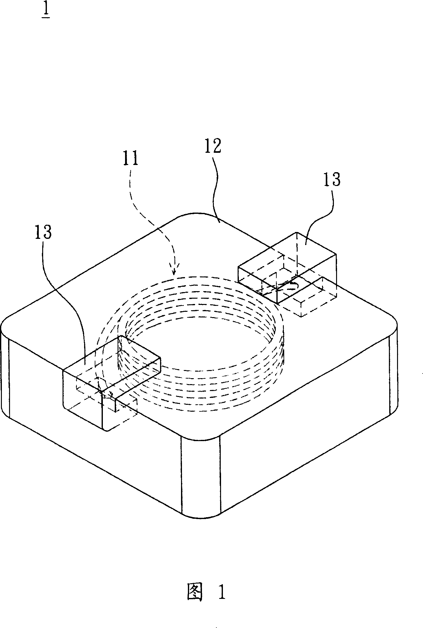
However, the coil 11 obtained by using the traditional winding method must leave a central gap because the central part cannot be wound, and the size of the coil 11 cannot be effectively reduced, so the thickness of the embedded inductor structure 1 is relatively large. , unable to meet the needs of component miniaturization
In addition, since the coil 11 cannot completely fill the space it is wound in, there is a certain limit to the number of turns of the coil under the same specification.

Method used


Image

  • Internal embedded type inductive structure and its producing method
  • Internal embedded type inductive structure and its producing method
  • Internal embedded type inductive structure and its producing method

Examples


Embodiment Construction

[0026] An embedded inductor structure and its manufacturing method according to preferred embodiments of the present invention will be described below with reference to related drawings, wherein the same elements will be described with the same reference symbols.

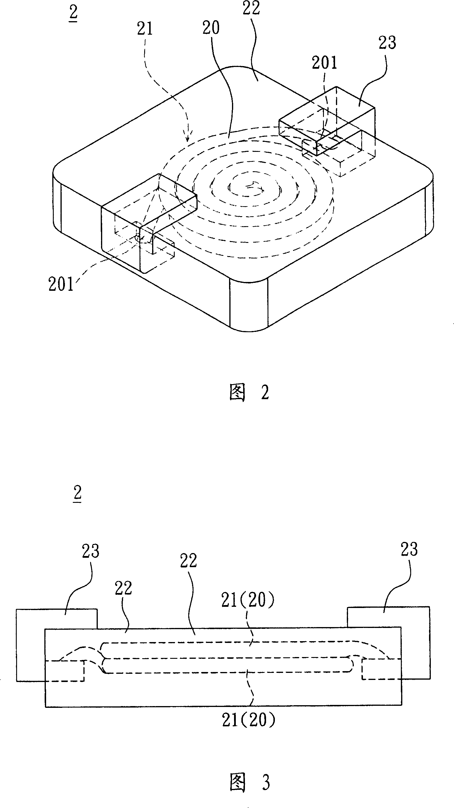
[0027] Please refer to FIG. 2 and FIG. 3 , which are a perspective view and a side view of an embedded inductor structure 2 according to a preferred embodiment of the present invention. The embedded inductor structure 2 includes at least one coil 21 , a magnetic body 22 and two terminals 23 .

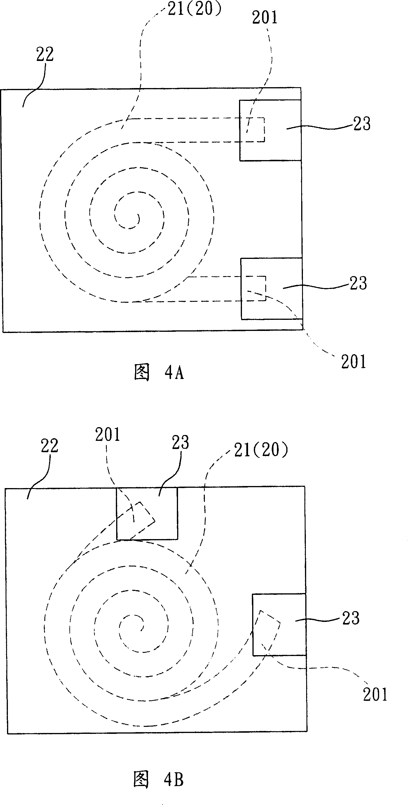
[0028] The coil 21 is formed by winding a conductive wire 20 from the middle section to the two ends 201 in a spiral manner, so that the coil 21 is tightly arranged in a spiral shape, so that more coils can be wound under the same volume condition Number, in order to achieve the effect of increasing the inductance value. Then the ends 201 are respectively connected to the terminals 23, as a structure for electrical connectio...


PUM

PropertyMeasurementUnit
angleaaaaaaaaaa

Abstract

The inner embedded type inductance structure includes a winding, and a magnetic body. Through a conductive wire, the winding is winded from middle part to two end parts. The winding is embedded inside the magnetic body.

Description

technical field [0001] The invention relates to an embedded inductance structure and a manufacturing method thereof, in particular to an embedded inductance structure in which a coil is spirally wound from a middle section to two ends and a manufacturing method thereof. Background technique [0002] With the miniaturization of electronic products, basic and important components such as inductor structures are also required to be reduced in size to meet the trend of miniaturization of components. [0003] Please refer to FIG. 1 , a conventional embedded inductor structure 1 has a coil 11 , a magnetic body 12 and two terminals 13 . Two ends of the coil 11 are respectively connected to the terminals 13 , and the magnetic body 12 covers the coil 11 . In addition, the terminals 13 are exposed to the magnetic body 12 to serve as pins of the embedded inductor structure 1 . [0004] The coil 11 is usually wound from one end to the other end by a conductive wire to form a hollow cy...

Claims


Application Information

Patent Timeline
Patent Type & Authority Applications(China)
IPC IPC(8): H01F17/00H01F27/28H01F41/00H01F41/04
Inventor 黄能贵高清满许汉正
Owner DELTA ELECTRONICS INC
Learn More