
Spindle unit and machining device

A technology for spindles and thrust bearings, which is applied in the direction of drive devices, shafts and bearings, grinding drives, etc., and can solve problems such as thermal deformation of the shell or spindle, inability to rotate the spindle, and narrow gaps

Pending Publication Date: 2022-03-01
DISCO CORP
View PDF2 Cites 0 Cited by
  • Summary
  • Abstract
  • Description
  • Claims
  • Application Information

AI Technical Summary

Problems solved by technology

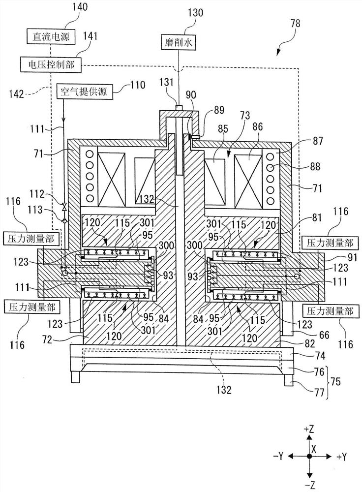
[0008] However, since the gap is narrow, thermal deformation of the casing or the main shaft may occur due to the supply of air for forming the air bearing, the passage of cooling water, etc., at the initial stage of device startup.
In this case, there is a contact portion where the main shaft and the case come into contact, and when the main shaft is rotated, the contact portion may rub against and form unevenness, and the main shaft may not be able to rotate.

Method used


Image

  • Spindle unit and machining device
  • Spindle unit and machining device
  • Spindle unit and machining device

Examples


Embodiment Construction

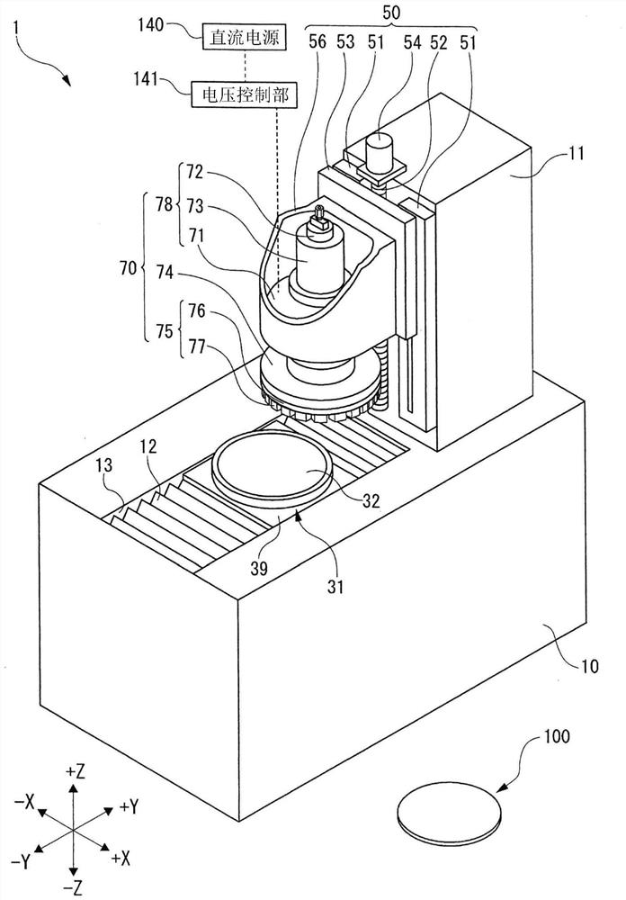
[0023] Hereinafter, embodiments of the present invention will be described with reference to the drawings. like figure 1 As shown, the grinding apparatus 1 of the present embodiment is an example of a processing apparatus, and is an apparatus for grinding a wafer 100 as a workpiece. The wafer 100 is, for example, a semiconductor wafer.

[0024] The grinding device 1 has a cuboid base 10 and a column 11 extending upward.

[0025] An opening 13 is provided on the upper surface side of the base 10 . In addition, a chuck table 31 as a holding unit is arranged in the opening 13 . The chuck table 31 has a holding surface 32 for holding the wafer 100 .

[0026] The holding surface 32 of the chuck table 31 is made of a porous material, and communicates with a suction source (not shown), whereby the wafer 100 is sucked and held. That is, the chuck table 31 holds the wafer 100 via the holding surface 32 .

[0027] In addition, the chuck table 31 can hold the wafer 100 by the holdi...


PUM


Abstract

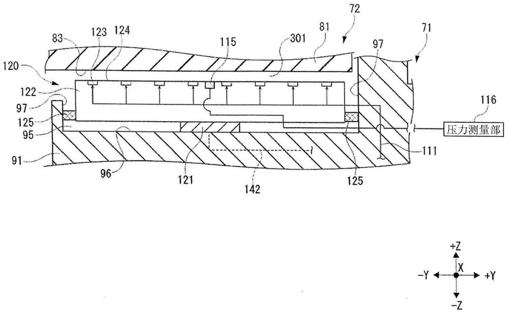
The invention provides a main shaft unit and a machining device. The main shaft unit is provided with an air bearing which enables a main shaft to continuously rotate even under the condition of thermal deformation and is excellent in load resistance. The main shaft unit includes a main shaft to which a machining tool is mounted at a tip end, and a main shaft housing having a thrust bearing and a radial bearing that rotatably support the main shaft by air in a non-contact manner, the thrust bearing having: an air supply unit that supplies air to the main shaft; the air supply part is used for supplying air to a gap between the outer side face of the main shaft and the inner side face of the main shaft shell in the direction perpendicular to the axial direction of the main shaft; and an adjusting part capable of adjusting the distance of the gap in the direction perpendicular to the outer side surface of the main shaft.

Description

technical field [0001] The invention relates to a spindle unit and a machining device. Background technique [0002] A grinding apparatus for grinding a wafer held by a chuck table includes a spindle unit including a spindle. In this grinding device, a grinding wheel on which a ring-shaped grinding wheel is arranged is attached to the front end of a main shaft. The wafer is ground by a grinding wheel that is rotated by rotating a spindle. [0003] As disclosed in Patent Document 1, the spindle unit includes: a spindle housing that forms a gap to surround the outer peripheral surface of the spindle; and an air supply unit that supplies air to the gap. The gap is filled with air and pressurized, thereby forming an air bearing. [0004] In addition, regarding the main shaft, as disclosed in Patent Document 2, by measuring the pressure of the air in the gap, it is possible to measure the load applied to the grinding wheel. [0005] Patent Document 1: Japanese Patent Applicat...

Claims


Application Information

Patent Timeline
Patent Type & Authority Applications(China)
IPC IPC(8): B24B7/22B24B41/04B24B49/00B24B55/00B24B55/02B24B47/12B24B41/06
CPCB24B7/228B24B41/047B24B49/00B24B55/00B24B55/02B24B47/12B24B41/068B24B49/08F16C32/0614F16C32/067F16C2233/00B23Q5/10H01L21/67092F16C17/04
Inventor 渡边裕之
Owner DISCO CORP
Learn More