Loop circuit filtering method

A loop filter and macroblock technology, applied in the field of digital video codec, can solve the problems of time-consuming off-chip data access operations and low image codec efficiency, and achieve the goal of reducing operation time and improving speed and efficiency Effect

Active Publication Date: 2007-07-25
HISENSE
View PDF0 Cites 6 Cited by
  • Summary
  • Abstract
  • Description
  • Claims
  • Application Information

AI Technical Summary

Problems solved by technology

However, as we all know, frequent access operations to off-chip data take a lot of time, so the efficiency of image encoding and decoding becomes low

Method used


Image

  • Loop circuit filtering method
  • Loop circuit filtering method
  • Loop circuit filtering method

Examples


Embodiment Construction

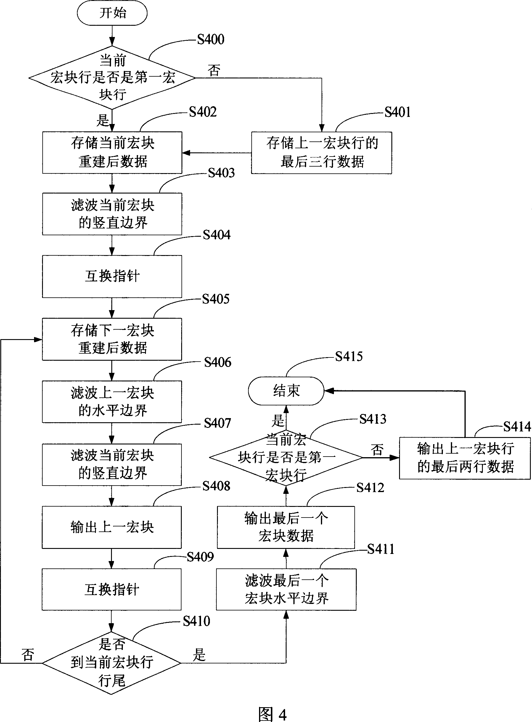
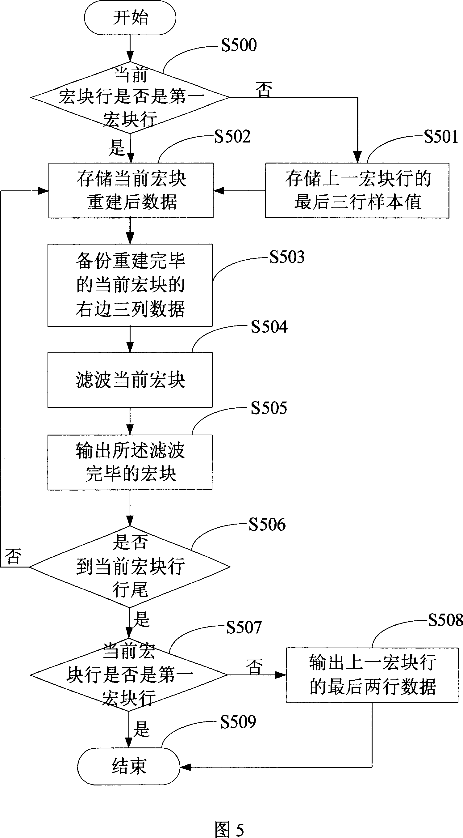
[0044] First, the working principle of the present invention is briefly described. In the process of image decoding, the present invention does not immediately output to the off-chip storage unit after reconstructing the macroblock, but performs loop filtering, and then outputs to the off-chip storage unit after the filtering operation. The present invention will be further described below in conjunction with the accompanying drawings.

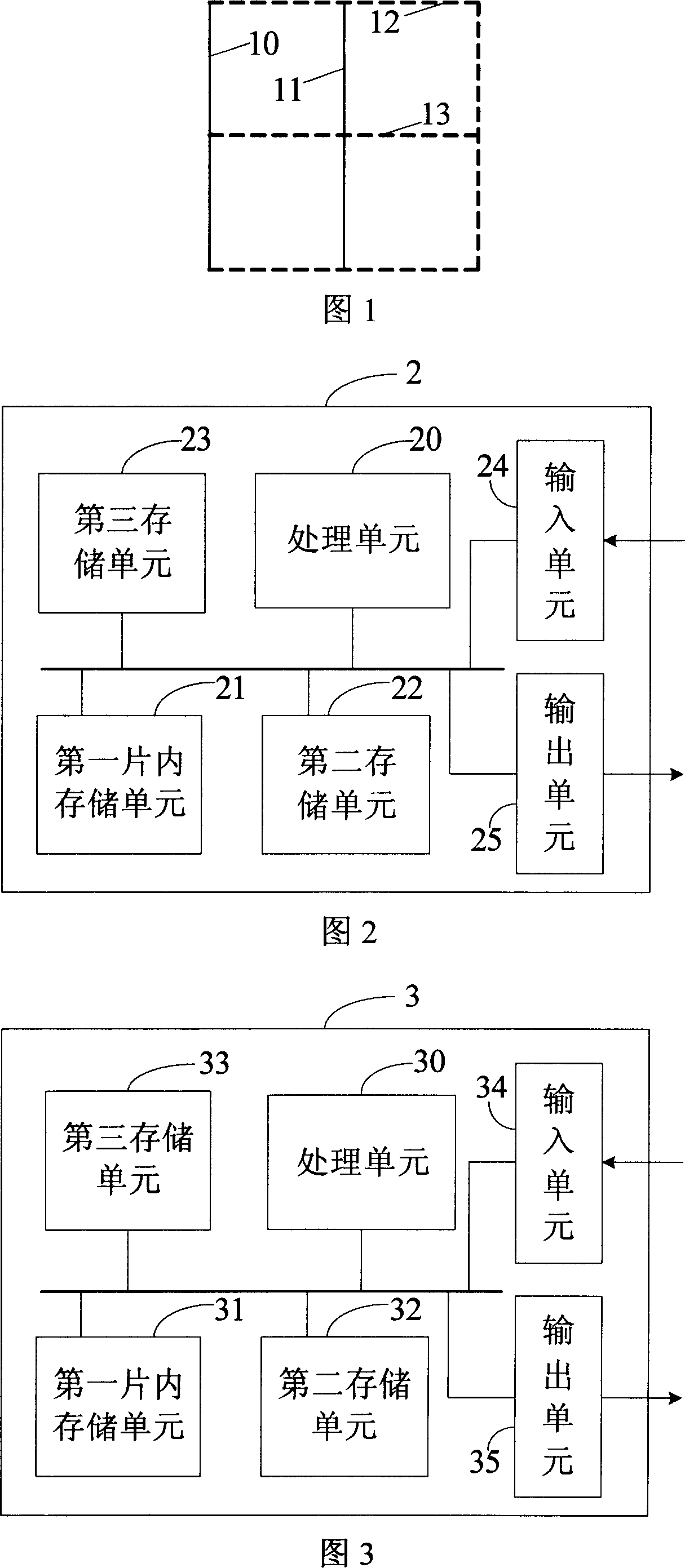
[0045] In order to better understand the present invention, some basic components of the processing chip are briefly drawn below, and the present invention is explained with the help of these functional block diagrams. Of course, the actual structure of the processing chip is very complicated, and this example only briefly selects some of its components to help understand the present invention, and the block diagram of the processing chip in this example should not limit the present invention.

[0046] Referring to Figure 2, there is illustra...


PUM


Abstract

The method comprises: the macro block finishing the reconstruction is not immediately sent out from the processing chip, and is made with filter operation; after filter operation, it is sent out from the processing chip. The invention saves the steps for outputting the macro block finishing the reconstruction and inputting macro block when making loop filer so as to improve the speed and efficiency of encode and decode.

Description

technical field [0001] The invention relates to digital video codec technology, in particular to a filtering method. Background technique [0002] A variety of current video codec standards, such as AVS and H.264, all use a macroblock-based coding framework for their video codec algorithms, which divide the input video into macroblocks for prediction, motion estimation, transformation, quantization, and entropy coding. Wait. Due to block, it will inevitably lead to virtual block effect, so the loop filter technology is introduced. [0003] All block boundaries of a macroblock shall be filtered except picture boundaries and slice boundaries. Here, the macroblock boundary is defined as the boundary of each block inside the macroblock (for example, AVS is 8*8 blocks). [0004] Loop filtering takes a macroblock as a unit, and for loop filtering in the prior art, refer to FIG. 1 . As shown in FIG. 1 , a schematic diagram of a macroblock. First, filter the vertical boundary f...

Claims


Application Information

Patent Timeline
Patent Type & Authority Applications(China)
IPC IPC(8): H04N7/26H04N7/24H04N19/82
Inventor 田树民裴雷
Owner HISENSE
Why Eureka
Try Eureka