Circuit used for acquiring bus current and station electricity emergency automatic switching device

A bus current and circuit technology, applied in the direction of circuit devices, measuring current/voltage, measuring devices, etc., can solve the problems of personal and equipment insulation threats, inconsistent technical specifications, and long time consumption, so as to reduce personal and equipment risks, Reduced time-consuming operation and simple installation

Inactive Publication Date: 2016-02-03
SHENZHEN POWER SUPPLY BUREAU
View PDF5 Cites 2 Cited by
  • Summary
  • Abstract
  • Description
  • Claims
  • Application Information

AI Technical Summary

Problems solved by technology

The existing current collection uses the current loop of the original fault backup self-switching device, that is, the prepared lead cable is used to lead the current from the original current loop to the newly put into use emergency backup self-switching device, but there are the following deficiencies : 1. In the process of leading the original current, it is necessary to short-circuit the current input terminal of the original fault standby self-switching device first, and then complete the current connection of the current transformer side of the newly put into use station power emergency standby self-switching device, Therefore, it is easy to cause misoperation of the original current circuit (ie, current transformer circuit) to open circuit, resulting in extremely high overvoltage, which poses a threat to personal and equipment insulation; The manufacturer's model and technical specifications of the emergency backup self-injection device are inconsistent, which may cause the operation and maintenance personnel to spend a long time in the process of finding the original current circuit and the position of the accessible terminal

Method used


Image

  • Circuit used for acquiring bus current and station electricity emergency automatic switching device
  • Circuit used for acquiring bus current and station electricity emergency automatic switching device
  • Circuit used for acquiring bus current and station electricity emergency automatic switching device

Examples


Embodiment Construction

[0023] In order to make the object, technical solution and advantages of the present invention clearer, the present invention will be further described in detail below in conjunction with the accompanying drawings.

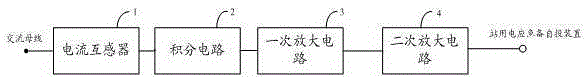
[0024] Such as Figure 1 to Figure 4 As shown, in Embodiment 1 of the present invention, a circuit for collecting bus current is provided, which cooperates with the AC bus (not shown). not shown), including a current transformer 1, an integrating circuit 2 and a primary amplifier circuit 3 connected in sequence; wherein,

[0025] The current transformer 1 is also connected to the AC bus;

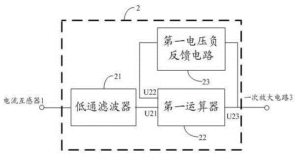
[0026] The integrating circuit 2 includes a low-pass filter 21, a first computing unit 22 and a first voltage negative feedback circuit 23; wherein, one end of the low-pass filter 21 is connected to the current transformer, and the other end is connected to the first computing unit 22 The input terminal U21 is connected; the second input terminal U22 of the first arithmetic un...


PUM


Abstract

The invention provides a circuit used for acquiring bus current. The circuit comprises a current transformer, an integrating circuit and a primary amplification circuit. The current transformer is connected with an alternating-current bus. The integrating circuit comprises a low-pass filter, a first calculator and a voltage negative feedback circuit. The first input end of the first calculator is connected with the current transformer via the low-pass filter. The first voltage negative feedback circuit is connected between the second input end and an output end. The output end is connected with the primary amplification circuit. The primary amplification circuit comprises a band-pass filter, a second calculator and a second voltage negative feedback circuit. The band-pass filter is parallelly connected with the second voltage negative feedback circuit, and the parallel branch is then connected with the integrating circuit and arranged between the first input end and the output end of the second calculator. The second input end of the second calculator is connected with an interior working voltage source and the output end is connected with an automatic switching device. In this way, misoperation of new station electricity emergency automatic switching devices can be reduced and operation time is reduced.

Description

technical field [0001] The invention relates to the technical field of current collection for a substation station system, in particular to a circuit for collecting bus current and a self-injection device for station power emergency backup. Background technique [0002] The power system of the substation station can provide stable and reliable 380V AC power supply for the AC load in the substation. The AC bus voltage comes from the main substation or the slave substation power supply. loss of pressure. Therefore, once the standby automatic switching device fails, the AC bus will face the risk of voltage loss. At this time, if there are multiple important loads in the station (such as communication power supply, main transformer cooling power supply, etc.) loss of voltage, it will cause the main transformer to trip, etc. Major accident. [0003] In order to reduce the above-mentioned risk of AC bus voltage loss, it is necessary to quickly dismantle or replace the fault back...

Claims


Application Information

Patent Timeline
Patent Type & Authority Applications(China)
IPC IPC(8): H02J9/04G01R19/00
Inventor 周永光佘楚云梁瑞利周潮
Owner SHENZHEN POWER SUPPLY BUREAU
Why Eureka
Try Eureka