Artificial femur structure

A femoral and artificial technology, applied in the direction of femoral head, bone implant, hip joint, etc., can solve the problem of reducing storage space, achieve the effect of reducing storage space, reducing medical expenses, and reducing costs

Inactive Publication Date: 2007-08-01
郑诚功
View PDF2 Cites 5 Cited by
  • Summary
  • Abstract
  • Description
  • Claims
  • Application Information

AI Technical Summary

Problems solved by technology

[0013] Another object of the present invention is to provide an artificial femur structure, the technical problem to be solved is to reduce the hospital storage space, use the artificial femoral stem as a separate design, and can change the angle required by the patient an...

Method used


Image

  • Artificial femur structure
  • Artificial femur structure
  • Artificial femur structure

Examples


Embodiment Construction

[0037] For further elaborating the technical means and effect that the present invention takes for reaching the intended invention purpose, below in conjunction with accompanying drawing and preferred embodiment, to its specific implementation, structure, feature and effect of the artificial femur structure that proposes according to the present invention, Details are as follows.

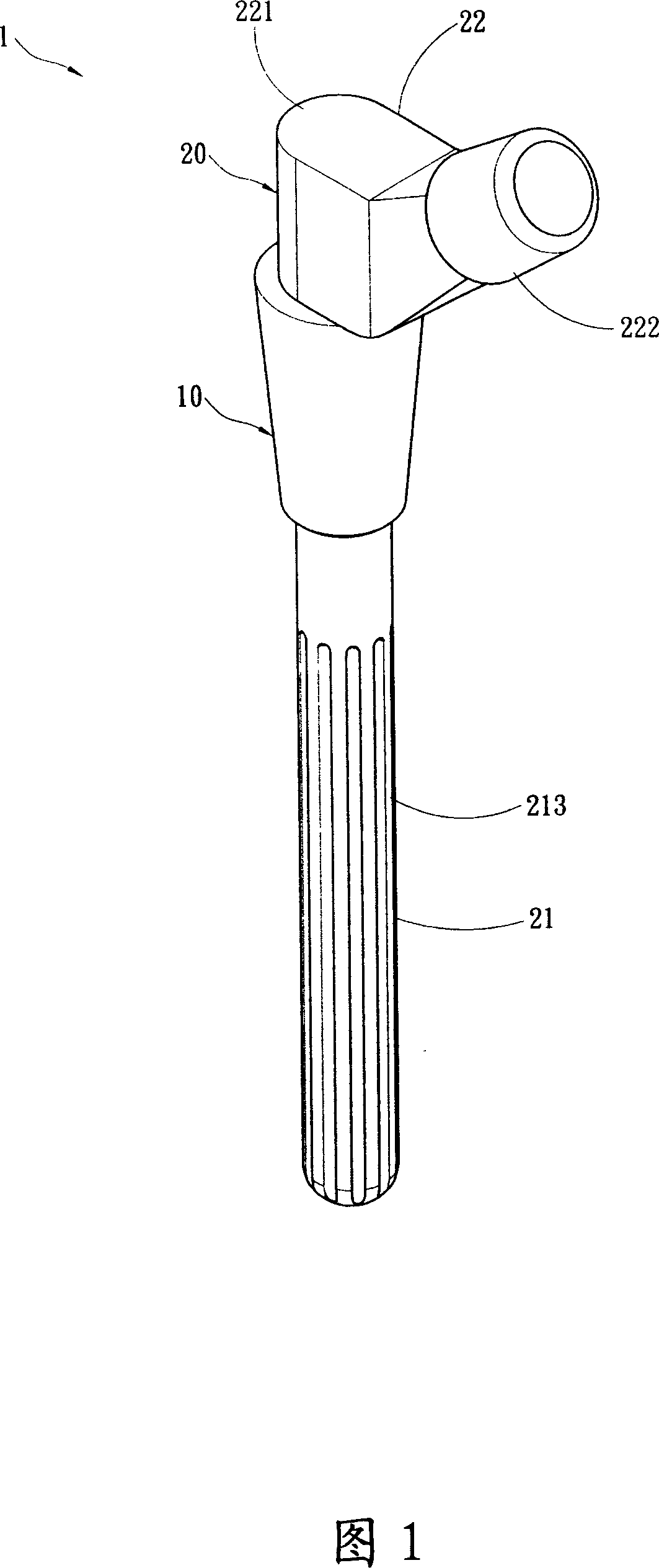
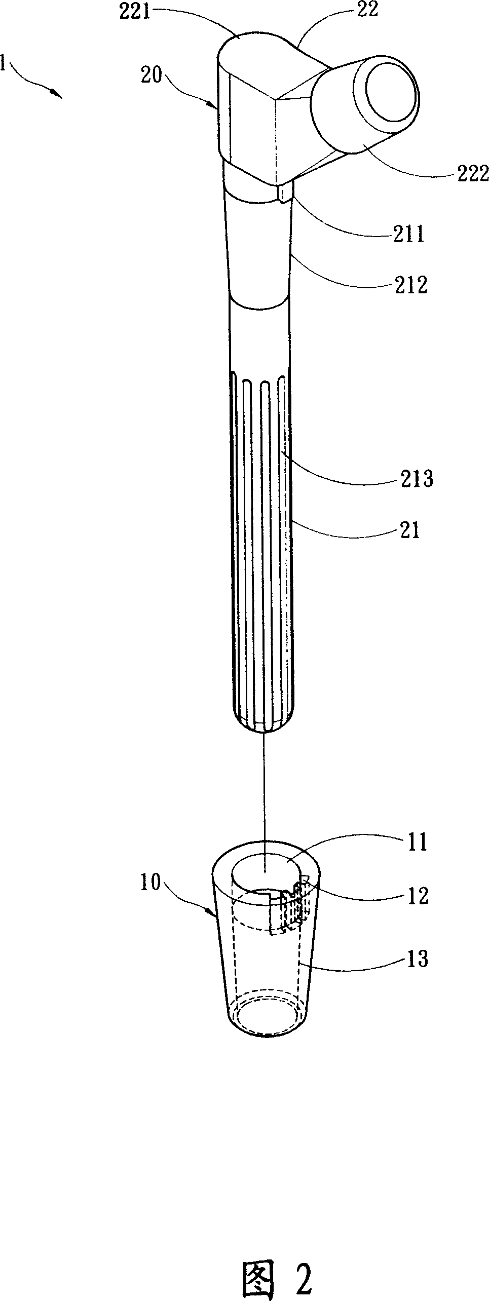
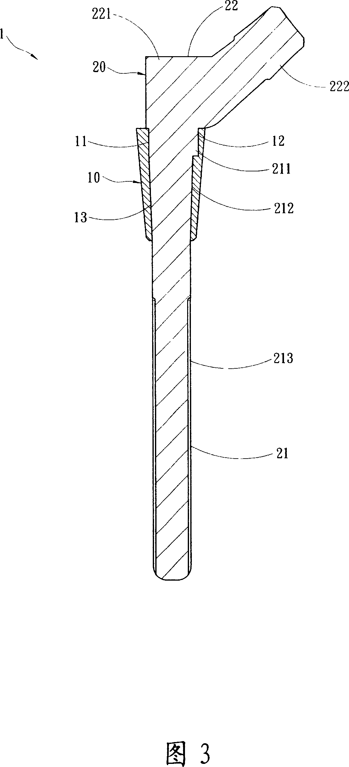
[0038] Please refer to FIG. 1 , FIG. 2 , and FIG. 3 , which are respectively an external perspective view, an exploded perspective view, and a schematic cross-sectional view of the artificial femur structure of the present invention. As shown in the figure, the present invention is a reconstructive structure used to replace the defect of the native femur bone after excision of the femoral head of the hip joint and its neck tissue. The artificial femur structure of the preferred embodiment of the present invention includes a base body 10 for filling the defect, and a support handle 20 assembled on th...


PUM


Abstract

The invention discloses an artificial femur structure, which comprises the following parts: chassis corresponding to fill defect, plural limit groove with hole on the periphery, support crank in the hole, joint end on one end of support crank, bone crank end on the other end with tapering segment, limit bond in the plural limit groove to define the position of joint end.

Description

technical field [0001] The invention relates to an artificial femur structure, in particular to an artificial femur structure used for human medical replacement. Background technique [0002] As humans age, the functions of various parts of the body tissue and organs gradually degenerate; and the femurs of the elderly, after years of use and wear, often cannot move like normal people, or due to osteoporosis, or accidents. Neck fracture cannot move; however, with the continuous advancement of medical technology, the problem of femoral wear and fracture can be replaced by artificial femoral medical materials; however, currently, for medical personnel and patients, it is possible to It is imperative to address the following long-standing problems: [0003] 1. After the artificial femur is implanted, whether the angle of the femur corresponding to the pelvis corresponds to the angle of the original femur, so the patient must bear the problem of adapting to the new femur angle; ...

Claims


Application Information

Patent Timeline
IPC IPC(8): A61F2/36A61F2/28
Inventor 郑诚功魏鸿文吕玉蓉
Owner 郑诚功
Why Eureka
Try Eureka