Master lock structure and combination door lock using the master lock structure

A main lock and door lock technology, applied in the field of locks, can solve the problems of inconvenient use, complex structure, long lock distance, etc., and achieve the effects of saving time, fast driving speed of the lock tongue, and increasing reliability.

Inactive Publication Date: 2007-08-01
联程机械(宁波)有限公司
View PDF5 Cites 7 Cited by
  • Summary
  • Abstract
  • Description
  • Claims
  • Application Information

AI Technical Summary

Problems solved by technology

There are many types of existing door locks, such as single, double insurance, multiple insurance, electronic alarm, etc., the structure and function of the above various door locks are all different, there are simple and complex, there are single There are also multi-functional ones; in the current structure of some multi-functional door locks, due to the relatively long locking stroke of the main bolt, usually the key needs to be turned twice to lock it completely, which is inconvenient and time-consuming to use, and the structure is also relatively complicated.

Method used


Image

  • Master lock structure and combination door lock using the master lock structure
  • Master lock structure and combination door lock using the master lock structure
  • Master lock structure and combination door lock using the master lock structure

Examples


Embodiment 1

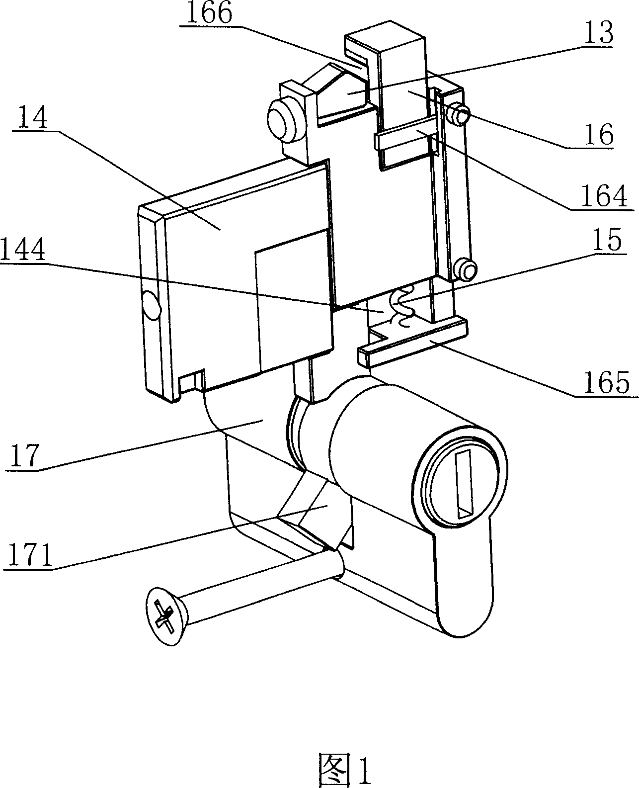
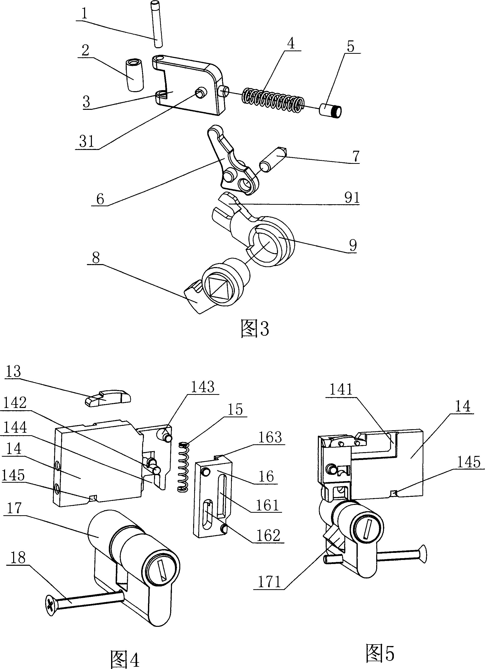
[0022] Embodiment 1: As shown in the figure, a main lock structure includes a lock tongue 14, a lock core 17 and a limit block 13. A lock tongue drive block 171 is provided on the lock core 17 coaxially, and a lock tongue 14 is provided with a The deadbolt driving groove 144 matched with the deadbolt driving block 171, the deadbolt 14 is provided with an adjusting block 16, and the adjusting block 16 is integrally provided with an upper baffle plate 164 and a lower baffle plate 165, and the upper baffle plate 164 is stuck on the lock. The upper end of the tongue 14, the lower baffle plate 165 is clamped on the dead bolt driving groove 144, an adjustment spring 15 is arranged between the dead bolt 14 and the upper end surface of the lower baffle plate 165, and the upper end of the adjustment block 16 is provided with a stopper 13 Cooperating limiting groove 166.

Embodiment 2

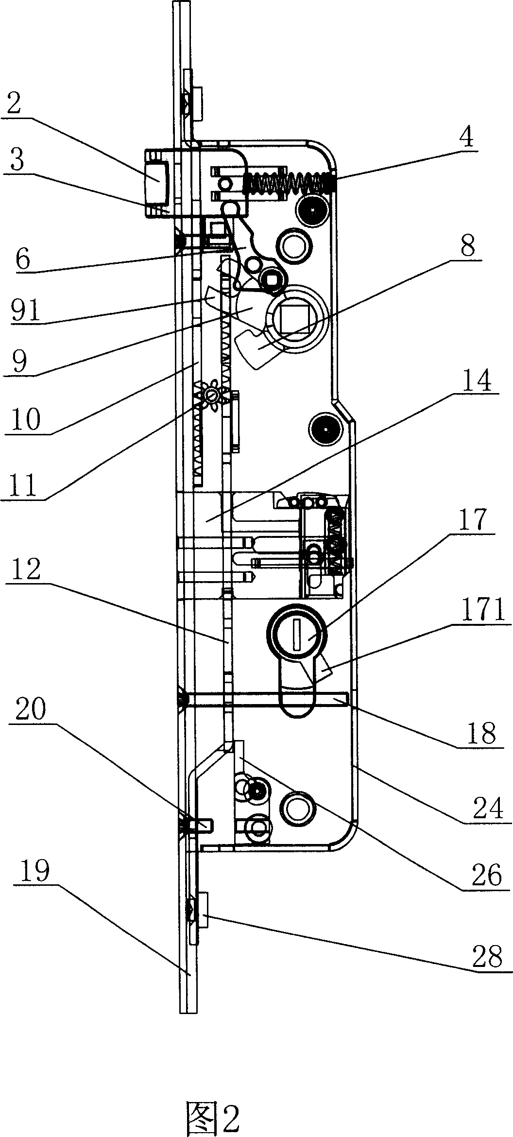
[0023] Embodiment 2: As shown in the figure, a combined door lock includes a base 24, a cover plate 21 and a side cover plate 19, the base 24 is fixed with a limit block 13, and the lock bolt 14 is integrally provided with a first guide Column 142 and spring column 143, adjusting block 16 is provided with spring groove 161 and the adjustment groove 162 that cooperates with first guide column 142 mutually, and spring column 143 is interconnected with adjustment spring 15 through spring groove 161, and one end of adjustment spring 15 Supported at the bottom of the spring groove 161, the upper end of the adjustment block 16 is provided with a limit projection 163 that cooperates with the limit block 13, and a lock cylinder 17 is provided under the lock tongue 14, and the lock cylinder 17 is fixed on the base 24 and the cover plate Between 21, the coaxial sleeve on the lock core 17 is provided with a deadbolt driving block 171, the deadbolt 14 is provided with a deadbolt driving gr...


PUM


Abstract

The invention discloses a main lock structure and relative combined door lock. The invention comprises a base, a cover plate and a side cover plate, wherein, the main lock and the auxiliary lock arranged between the base and the cover plate; the auxiliary comprises upper and lower locks; the main lock comprises a bolt, a lock element and a limiting block; the lock element is coaxially arranged with a bolt diving block; the bolt is arranged with a bolt driving groove engaged with the bolt driving block. The invention is characterized in that the bolt is arranged with an adjusting block, while a flexible device is arranged between the adjusting block and the bolt. The invention has the advantages in safety, reliability and simple structure. Via the flexible device between the bolt and the adjusting block, user can rotate key only for 270degree to jump out the bolt and lock the door. The lock device between the bolt and the upper and lower locks can avoid error lock.

Description

technical field [0001] The invention relates to a lock, in particular to a main lock structure and a combined door lock using the main lock structure. Background technique [0002] Lock is requisite a kind of antitheft tool in people's life, adorn a lock on door and window, can prevent that thief enters house and steals. There are many types of existing door locks, such as single, double insurance, multiple insurance, electronic alarm, etc., the structure and function of the above various door locks are all different, there are simple and complex, there are single There are also multi-functional ones; in the current structure of some multi-functional door locks, due to the relatively long locking stroke of the main bolt, usually the key needs to be turned twice to lock it completely, which is inconvenient and time-consuming to use, and the structure is also relatively complicated. . Contents of the invention [0003] The technical problem to be solved by the present inve...

Claims


Application Information

Patent Timeline
IPC IPC(8): E05B63/14
CPCE05C9/041E05B59/00E05B17/007E05B63/0017E05C9/004E05B63/18E05C9/047E05B17/2057
Inventor 庄子平
Owner 联程机械(宁波)有限公司
Why Eureka
Try Eureka